Automatic take-up device for electric power engineering

A wire take-up device and power engineering technology, applied in the field of power engineering, can solve problems such as skewed twisting of cables, heavy workload of staff, and low efficiency of wire take-up, and achieve the effect of avoiding oblique winding

Inactive Publication Date: 2022-03-18
承德石油高等专科学校
View PDF0 Cites 4 Cited by
  • Summary
  • Abstract
  • Description
  • Claims
  • Application Information

AI Technical Summary

Problems solved by technology

The take-up reel is a kind of cable storage tool. Most of the existing take-up reels are manually rotated by the staff to take up the wires. The workload of the staff is large, the efficiency of the take-up is low, and it is impossible to ensure that the wires can be wound gradually and evenly. on the surface of the reel
[0003] The automatic wire take-up device for electric power engineering in the prior art generally includes a frame, on which there is a column interspersed with a wire coil, and a rotating disc is fixedly connected under the column, and the rotating disc is fixedly connected to the chassis of the frame through a bearing, and the chassis There is a positioning hook at the bottom that can be hung horizontally, but there are certain defects in the existing technology. When the automatic take-up device handles cables, it often encounters the situation that the cables are suddenly stuck, which will not only affect the efficiency of cable storage , there will also be a risk of cable damage; the main reason is that other substances are often adhered to the surface of the cable, causing the problem of skewed twisting of the cable during storage, so it is necessary to perform effective cleaning and positioning correction when the cable is stored

Method used


Image

  • Automatic take-up device for electric power engineering
  • Automatic take-up device for electric power engineering
  • Automatic take-up device for electric power engineering

Examples


Embodiment Construction

[0026] The technical solutions in the embodiments of the present invention will be clearly and completely described below in conjunction with the accompanying drawings in the embodiments of the present invention, examples of which are shown in the accompanying drawings. When the following description refers to the accompanying drawings, the same numerals in different drawings refer to the same or like elements unless otherwise indicated.

[0027] Apparently, the described embodiments are only some of the embodiments of the present invention, but not all of them. Based on the embodiments of the present invention, all other embodiments obtained by persons of ordinary skill in the art without making creative efforts belong to the protection scope of the present invention.

[0028] The specific implementation of the present invention will be described in detail below in conjunction with specific embodiments.

[0029] In one embodiment;

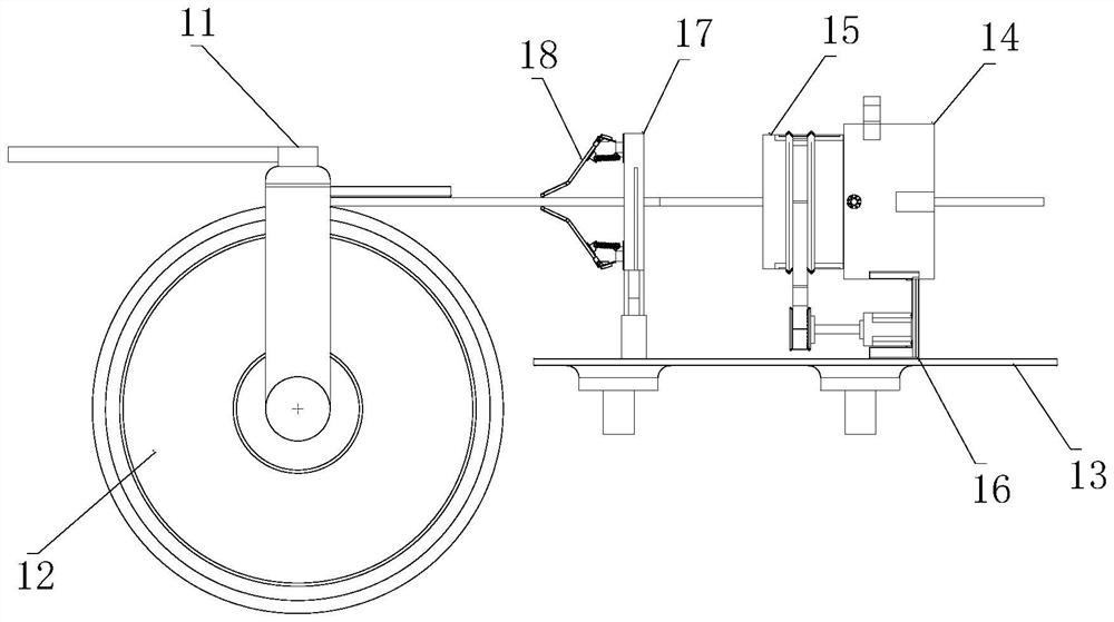
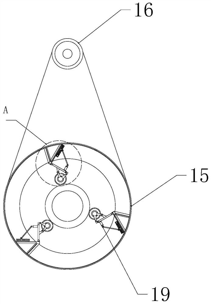
[0030] see figure 1 with figure 2 , pr...


PUM


Abstract

The invention relates to the technical field of electric power engineering, in particular to an automatic take-up device for electric power engineering, which comprises an equipment bracket, a take-up reel mounted on the equipment bracket, and a connecting frame in butt joint with the take-up reel, the connecting frame is provided with a guide machine barrel which is arranged at the cable receiving end of the connecting frame; a cleaning machine barrel is rotatably mounted in the guide machine barrel, a driving assembly used for driving the cleaning machine barrel is arranged on the side edge of the guide machine barrel, a cable extends into an inner cavity of the guide machine barrel and penetrates into the inner axis position of the cleaning machine barrel, and a plurality of cleaning parts are arranged in an inner cavity of the cleaning machine barrel at equal angles; and the positioning machine part is arranged between the take-up reel and the guide machine barrel, the positioning machine part is located at the take-up end of the take-up reel, two correction assemblies are arranged on the take-up reel, and the correction assemblies are attached to the two sides of the cable and are arranged in a mirror image mode. According to the cable take-up device, during take-up, mutual adhesion objects such as soil on the surface of a cable are effectively removed, the cable is corrected, and therefore the problem that the cable is obliquely wound during storage is solved.

Description

technical field [0001] The invention relates to the technical field of electric power engineering, in particular to an automatic wire take-up device for electric power engineering. Background technique [0002] Electric power engineering refers to engineering related to the production, transmission, and distribution of electric energy. In a broad sense, it also includes engineering that uses electricity as power and energy in various fields. The take-up reel is a kind of cable storage tool. Most of the existing take-up reels are manually rotated by the staff to take up the wires. The workload of the staff is large, the efficiency of the take-up is low, and it is impossible to ensure that the wires can be wound gradually and evenly. on the surface of the reel. [0003] The automatic wire take-up device for electric power engineering in the prior art generally includes a frame, on which there is a column interspersed with a wire coil, and a rotating disc is fixedly connected ...

Claims


Application Information

Patent Timeline
Patent Type & Authority Applications(China)
IPC IPC(8): B65H75/44B08B1/02
CPCB65H75/4402B08B1/02B65H2701/34
Inventor 邬连学张红玉
Owner 承德石油高等专科学校
Why Eureka
Try Eureka