
Nylon rope tensile resistance testing device capable of being monitored

A testing device and a tensile force-resisting technology, which is applied to measuring devices, instruments, scientific instruments, etc., can solve the problems of inconvenience to accurately adjust the distance of the drawstring, inconvenient to fix the nylon rope, and inconvenient to fix the positioning of the device, so as to facilitate accurate stretching. Adjustment operation, convenient and convenient operation, simple and efficient device structure

Inactive Publication Date: 2022-03-18
江苏亚昇制绳有限公司
View PDF0 Cites 0 Cited by
  • Summary
  • Abstract
  • Description
  • Claims
  • Application Information

AI Technical Summary

Problems solved by technology

[0005] In order to make up for the shortcomings of the existing technology, it solves the problems that it is not convenient to fix and position the device, it is not convenient to fix the nylon rope, and it is not convenient to accurately adjust the distance of the pull rope to the device

Method used


Image

  • Nylon rope tensile resistance testing device capable of being monitored
  • Nylon rope tensile resistance testing device capable of being monitored
  • Nylon rope tensile resistance testing device capable of being monitored

Examples


Embodiment 1

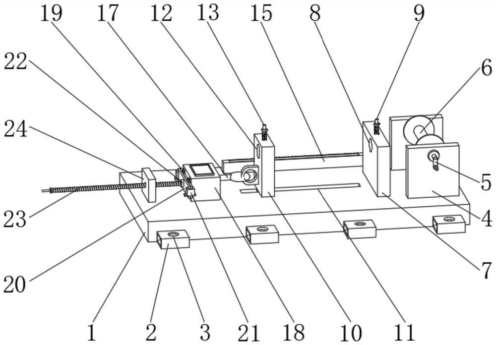
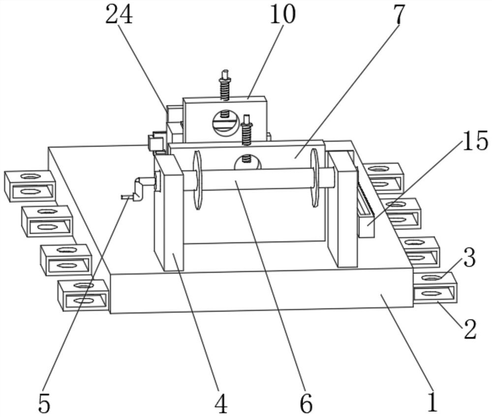
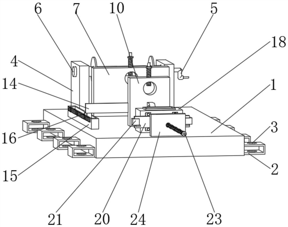
[0027] see figure 2 and Figure 5 As shown, a monitorable nylon rope tensile testing device includes a base plate 1 and a fixed vertical plate 7, the side of the base plate 1 is provided with an connecting plate 2, and the inner side of the connecting plate 2 is provided with a mounting hole 3, the base plate 1 The top of the top is provided with a fixed plate 4, and the outer wall of the fixed plate 4 is provided with a rotating handle 5, and the end of the rotating handle 5 is provided with a winding roller 6.

[0028] There are two installation holes 3 parallel to the inner side of the connecting plate 2, and four pairs of connecting plates 2 are arranged symmetrically with respect to the central axis of the bottom plate 1; the user can realize the installation of the bottom plate 1 through the setting of the connecting plate 2 and the installation hole 3 And fixed, so as to effectively improve the installation and stability of the device, so as to avoid the deviation of ...

Embodiment 2

[0031] see Figure 1-5 As shown, compared with Example 1, as another embodiment of the present invention, the fixed vertical plate 7 is arranged on the side of the fixed plate 4, and the inner side of the fixed vertical plate 7 is provided with a first fixing hole 8, and the fixed vertical plate The top of 7 runs through a first fixing screw 9, the side of the fixed vertical plate 7 is provided with a mobile vertical plate 10, and the bottom of the mobile vertical plate 10 is provided with a sliding rail 11, and the inner side of the mobile vertical plate 10 is provided with a second fixing hole 12, and the top of the moving vertical plate 10 is penetrated with a second fixed screw 13, the side of the moving vertical plate 10 is connected with a connecting plate 14, and the bottom of the connecting plate 14 is provided with a scale seat 15, and the end of the connecting plate 14 is provided with There is an indicator 16, the outer wall of the mobile vertical plate 10 is provid...


PUM


Abstract

The invention belongs to the field of tensile resistance testing devices, and particularly relates to a monitorable nylon rope tensile resistance testing device which comprises a bottom plate and a fixed vertical plate, a connecting plate is arranged on the side of the bottom plate, a mounting hole is formed in the inner side of the connecting plate, a fixed plate is arranged at the top of the bottom plate, and a rotating handle is arranged on the outer wall of the fixed plate. The fixed vertical plate is arranged on the side of the fixed plate, a first fixed hole is formed in the inner side of the fixed vertical plate, a first fixed screw rod penetrates through the top of the fixed vertical plate, a movable vertical plate is arranged on the side of the fixed vertical plate, and a sliding rail is arranged at the bottom of the movable vertical plate; a second fixing hole is formed in the inner side of the movable vertical plate, and a second fixing screw rod penetrates through the top of the movable vertical plate; the device can be conveniently fixed and positioned, a nylon rope can be conveniently fixed, and the rope pulling distance of the device can be conveniently and accurately adjusted.

Description

technical field [0001] The invention relates to the field of tensile testing devices, in particular to a monitorable nylon rope tensile testing device. Background technique [0002] Tensile tester is an instrument for tensile testing, mainly used for non-metallic materials such as tapes, rubber, plastics, sea / foam, waterproof materials, wires and cables, textiles, net ropes, non-woven fabrics, and metal wires, metal foils, metals, etc. Tensile, compression, bending, peeling, shearing, and tearing tests of plates and metal rods are indeed sharp tools to help the industry improve quality. [0003] The traditional tensile testing device has the problems of inconvenient fixing and positioning of the device, inconvenient operation of fixing the nylon rope, and inconvenient precise adjustment of the pulling distance of the device. [0004] Therefore, in view of the above problems, a monitorable nylon rope tensile testing device is proposed. Contents of the invention [0005] I...

Claims


Application Information

Patent Timeline
Patent Type & Authority Applications(China)
IPC IPC(8): G01N3/00G01N3/02G01N3/04
CPCG01N3/00G01N3/02G01N3/04G01N2203/0003G01N2203/028G01N2203/0605G01N2203/0682G01N2203/0423
Inventor 孙静严素琴梁俊
Owner 江苏亚昇制绳有限公司
Learn More