Eureka AIR delivers breakthrough ideas for toughest innovation challenges, trusted by R&D personnel around the world.

Large-scale array antenna based on virtual array

An array antenna and virtual array technology, which is applied in the field of array antennas, can solve the problems of complex systems, large-scale array antenna arrays, and high costs, and achieve the effects of high resolution accuracy, large array aperture, and overall machine cost control

Pending Publication Date: 2022-03-18
CHINA ELECTRONICS TECH GRP CORP NO 14 RES INST
View PDF8 Cites 0 Cited by
  • Summary
  • Abstract
  • Description
  • Claims
  • Application Information

AI Technical Summary

Problems solved by technology

[0004] The purpose of this application is to solve the problem of complex system and high cost in the millimeter wave imaging system due to the large scale of the array antenna array and the large number of channels

Method used


Image

  • Large-scale array antenna based on virtual array
  • Large-scale array antenna based on virtual array
  • Large-scale array antenna based on virtual array

Examples


Embodiment Construction

[0018] In order to better understand the above-mentioned purpose, features and advantages of the present application, the present application will be further described in detail below in conjunction with the accompanying drawings and specific embodiments. It should be noted that, in the case of no conflict, the embodiments of the present application and the features in the embodiments can be combined with each other.

[0019] In the following description, a lot of specific details are set forth in order to fully understand the application, however, the application can also be implemented in other ways different from those described here, therefore, the protection scope of the application is not limited by the following disclosure Limitations of specific embodiments.

[0020] In this embodiment, in order to form a narrow beam, the W-band millimeter-wave imaging system needs to have a large array aperture, which significantly increases the system complexity and overall machine c...


PUM


Abstract

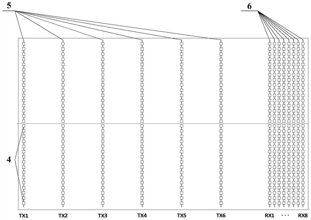
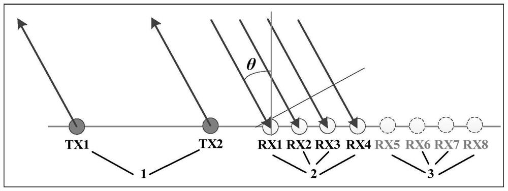
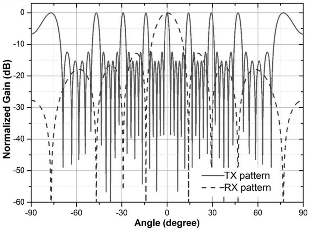
The invention discloses a large-scale array antenna based on a virtual array. The array antenna comprises a transmitting linear array and a receiving linear array, the number of channels of the transmitting linear array is 12, the transmitting linear array is arranged on the left side of the array antenna, the transmitting linear array is composed of upper and lower symmetrical channels, and the upper and lower symmetrical channels of the transmitting linear array are 6 columns * 2 rows of channels; the number of channels of the receiving linear array is 16, the receiving linear array is arranged on the right side of the array antenna, the receiving linear array is composed of upper and lower symmetrical channels, and the upper and lower symmetrical channels of the receiving linear array are 8 columns * 2 rows, a first interval between two adjacent channels in the transmitting linear array is four times of a second interval between two adjacent channels in the receiving linear array, the channels in the transmitting linear array are configured to work in a time-sharing manner, and the receiving linear array is configured to work at the same time. According to the technical scheme of the invention, the problems of large array scale and numerous channels of an array antenna in a millimeter wave imaging system are solved.

Description

technical field [0001] The present application relates to the technical field of array antennas, and in particular, to a large-scale array antenna based on a virtual array. Background technique [0002] In recent years, with the rapid development of solid-state microwave devices and microwave integrated circuits, the application requirements of millimeter wave detection and imaging technology have become increasingly urgent, especially in the fields of automatic driving of automobiles, security checks at airports and stations. Among them, the millimeter-wave imaging system whose operating frequency is in the W-band has been more applied due to factors such as short wavelength and large bandwidth. This type of millimeter-wave imaging system has the ability to image the target with high precision. [0003] In order to achieve this goal, this type of system needs to have a large array aperture, so as to meet the narrow beam required by the system. This will make the millimete...

Claims


Application Information

Patent Timeline
Patent Type & Authority Applications(China)
IPC IPC(8): H01Q21/00H01Q1/38
CPCH01Q21/00H01Q1/38Y02D30/70
Inventor 李斌张金平胡啸邓晔马天野
Owner CHINA ELECTRONICS TECH GRP CORP NO 14 RES INST
Why Eureka
Eureka Blog
Learn More