Guide pipe connecting structure capable of eliminating torque and achieving uniform bearing and fuel assembly
A connection structure and guide tube technology, which is applied in the assembly of connecting components, fuel elements, and greenhouse gas reduction, etc., can solve the problem that the connection gap between the guide tube and the upper tube seat cannot be guaranteed to be consistent, the bearing capacity of the guide tube is not exerted, and the guide tube is not used. Pipe carrying capacity and other issues, to achieve the effect of repeated disassembly and safe self-locking, improving disassembly and assembly efficiency, and eliminating potential safety hazards
- Summary
- Abstract
- Description
- Claims
- Application Information
AI Technical Summary
Problems solved by technology
Method used
Image
Examples
Embodiment 1
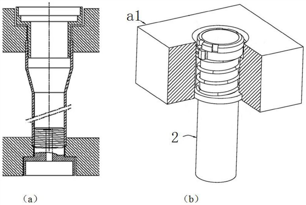
[0060] like figure 2 As shown, the existing connection structure has problems such as uneven loading of the guide tubes and limited bearing capacity. This embodiment proposes a connection structure of the guide tubes that eliminates the torque and evenly loads the load.
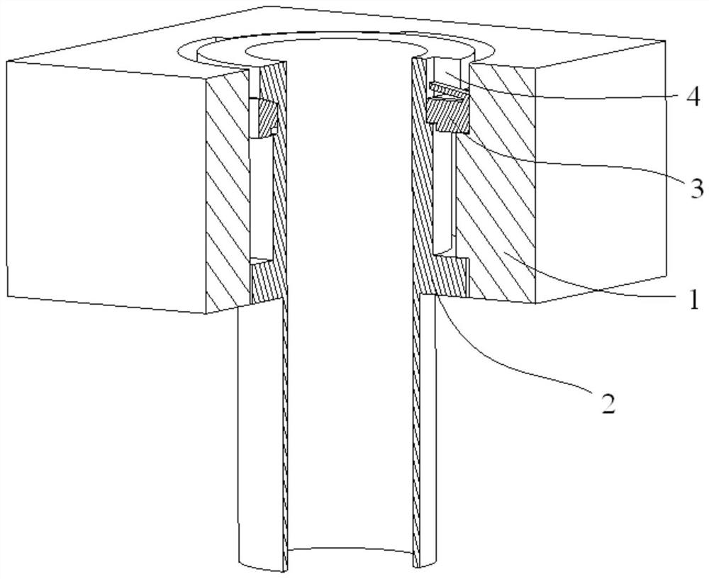
[0061] like image 3 As shown, the connection structure of this embodiment is composed of an upper connection structure and a lower connection structure; the upper connection structure is mainly composed of an open suspension sleeve 3, a bearing sleeve 4 and a corresponding upper pipe seat installation hole 1, and the upper end of the guide pipe 2 is provided with limited Position ring, the upper end of the guide tube 2 is detachably installed in the installation hole of the upper pipe seat through the open suspension sleeve and the bearing sleeve, and the open suspension sleeve and the load sleeve adopt a tapered surface to cooperate, and the opening size of the open suspension sleeve is adjusted. Stepless...
Embodiment 2
[0068] When the connection load is relatively small, this embodiment compensates the height tolerance of the upper pipe seat installation hole and the connection structure by setting an elastic structure with moderate stiffness such as a disc spring between the open suspension sleeve 3 and the load sleeve 4, thereby canceling The opening of the opening suspension sleeve proposed in Embodiment 1 cooperates with the tapered surface, which simplifies the manufacture of the connecting structure and reduces the cost.
Embodiment 3
[0070] like Figure 4-6As shown, this embodiment further optimizes the above-mentioned embodiment 1. The hanging hole 13 in the mounting hole of the upper pipe seat of this embodiment is designed as an incomplete stop structure 131 in the circumferential direction, providing the working position of the open hanging sleeve limit. A transition slope 122 is designed at the corner of the through hole 12, so that the open suspension sleeve 3 can be smoothly rotated to the working position. When installing, rotate the open suspension sleeve 3 clockwise to the side wall of the suspension hole 13, and then limit it by the limit structure 131; when disassembling, press down the elastic limit structure 34, and rotate the open suspension sleeve 3 counterclockwise to the upper pipe seat The position-limiting structure 131 of the installation hole, the opening suspension sleeve loses support and realizes dismounting. The protruding section of the bearing sleeve is radially provided with ...
PUM
 Abstract
Description
Claims
Application Information
 - R&D
- Intellectual Property
- Life Sciences
- Materials
- Tech Scout
- Unparalleled Data Quality
- Higher Quality Content
- 60% Fewer Hallucinations
Browse by: Latest US Patents, China's latest patents, Technical Efficacy Thesaurus, Application Domain, Technology Topic, Popular Technical Reports.
© 2025 PatSnap. All rights reserved.Legal|Privacy policy|Modern Slavery Act Transparency Statement|Sitemap|About US| Contact US: help@patsnap.com


