
Display panel and preparation method thereof

A display panel and plane technology, which is applied in semiconductor/solid-state device manufacturing, semiconductor devices, electrical components, etc., can solve problems that affect the light output efficiency of display products, and can not output light loss, etc., to achieve the effect of improving the display effect and improving the output efficiency

Active Publication Date: 2022-03-22
CHANGSHA HKC OPTOELECTRONICS CO LTD +1
View PDF7 Cites 2 Cited by
  • Summary
  • Abstract
  • Description
  • Claims
  • Application Information

AI Technical Summary

Problems solved by technology

The light emitted by the light-emitting layer passes through the anode / cathode, organic / inorganic film and then emerges from the light-emitting surface. Due to the difference in refractive index between the air, most of the light output in the vertical downward direction or in the vertical downward direction can be effectively output, and part of the light output in the horizontal direction or in the horizontal direction will be eliminated. Blocked in the film layer, resulting in the loss of light that cannot be output, which seriously affects the light extraction efficiency of the display product

Method used


Image

  • Display panel and preparation method thereof
  • Display panel and preparation method thereof
  • Display panel and preparation method thereof

Examples


Embodiment Construction

[0022] Features and exemplary embodiments of various aspects of the present application will be described in detail below. In the following detailed description, numerous specific details are set forth in order to provide a thorough understanding of the application. It will be apparent, however, to one skilled in the art that the present application may be practiced without some of these specific details. The following description of the embodiments is only to provide a better understanding of the present application by showing examples of the present application. In the drawings and the following description, at least some well-known structures and techniques have not been shown in order to avoid unnecessarily obscuring the application; and, for clarity, the dimensions of domain structures may have been exaggerated. Furthermore, the features, structures, or characteristics described hereinafter may be combined in any suitable manner in one or more embodiments.

[0023] The ...


PUM


Abstract

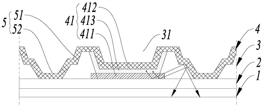
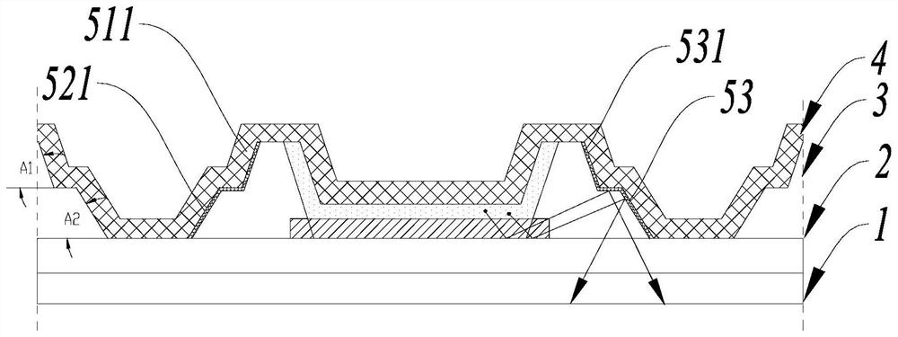
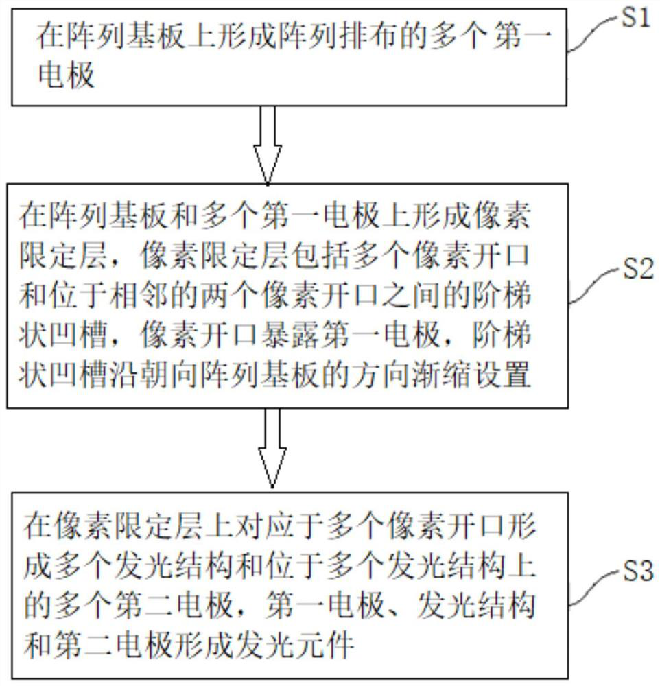
The invention relates to a display panel and a preparation method thereof. The display panel comprises an array substrate, a pixel limiting layer located on the array substrate and a light-emitting functional layer located on the side, away from the array substrate, of the pixel limiting layer, the pixel limiting layer comprises a plurality of pixel openings arranged in an array mode, and the light-emitting functional layer comprises a plurality of light-emitting elements. The light-emitting element comprises a first electrode, a light-emitting structure located on the first electrode and a second electrode located on the light-emitting structure, the second electrode is located on the side, away from the array substrate, of the first electrode, the first electrode is exposed out of the pixel openings, the pixel limiting layer further comprises a step-shaped groove located between every two adjacent pixel openings, and the step-shaped groove is located between every two adjacent pixel openings. The step-shaped groove is arranged in a gradually-shrinking mode in the direction towards the array substrate. According to the display panel, the light emitting efficiency is improved, and the display effect is improved.

Description

technical field [0001] The present application relates to the field of display technology, in particular to a display panel and a manufacturing method thereof. Background technique [0002] Organic electroluminescence (OLED, Organic Light Emitting Diode) is a phenomenon in which organic materials are excited by electrical energy to emit light. The light emitted by the light-emitting layer passes through the anode / cathode, organic / inorganic film and then emerges from the light-emitting surface. Due to the difference in refractive index between the air, most of the light output in the vertical downward direction or in the vertical downward direction can be effectively output, and part of the light output in the horizontal direction or in the horizontal direction will be eliminated. Blocked in the film layer, resulting in the loss of light that cannot be output, which seriously affects the light extraction efficiency of the display product. Contents of the invention [0003...

Claims


Application Information

Patent Timeline
Patent Type & Authority Applications(China)
IPC IPC(8): H01L51/52H01L27/32H01L51/56
CPCH10K59/122H10K50/856H10K59/1201H10K71/00
Inventor 黄淳載唐波玲李荣荣
Owner CHANGSHA HKC OPTOELECTRONICS CO LTD
Learn More