Supercharge Your Innovation With Domain-Expert AI Agents!

Annular steel wire winding equipment for steel cylinder concrete pipeline

A technology for steel cylinders and pipes, applied in the field of concrete pipes, can solve the problems of reduced steel wire continuity, weak wire winding, easy loosening, etc., and achieve the effects of improving continuity, avoiding breakpoints, and avoiding loosening.

Pending Publication Date: 2022-03-25
吴充权
View PDF0 Cites 0 Cited by
  • Summary
  • Abstract
  • Description
  • Claims
  • Application Information

AI Technical Summary

Problems solved by technology

[0004] In order to overcome the shortcoming that when the steel wire is wound outside the concrete tube core of the steel cylinder, it is very easy to cause a break point of the steel wire, resulting in a decrease in the continuity of the steel wire, and at the same time, the steel wire is easily loosened after winding, resulting in an unstable winding of the steel wire, the invention provides a steel cylinder Concrete pipe hoop winding steel wire equipment

Method used


Image

  • Annular steel wire winding equipment for steel cylinder concrete pipeline
  • Annular steel wire winding equipment for steel cylinder concrete pipeline
  • Annular steel wire winding equipment for steel cylinder concrete pipeline

Examples


Embodiment 1

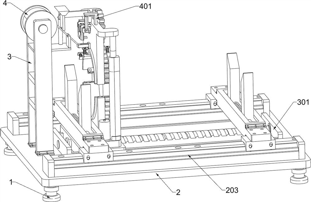
[0029] A steel cylinder concrete pipeline hoop-type winding steel wire equipment, according to Figure 1-2 As shown, it includes a support foot 1, a load bearing plate 2, a first fixed frame 3, a wire wheel 4, a limit unit and a wire winding unit; the upper part of the four support feet 1 is fixedly connected with a load bearing plate 2; The first fixed frame 3 is connected; the upper part of the first fixed frame 3 is equipped with a wire wheel 4; the upper surface of the load bearing plate 2 is connected with the limit unit; the middle part of the upper surface of the load bearing plate 2 is connected with a wire winding unit; .

[0030] When working, the staff will move the load-bearing plate 2 to the position to be used, and keep the four feet 1 level, and then the staff will place the steel cylinder concrete tube core in the limit unit, and pass through the limit unit Limit the steel cylinder concrete tube core, place the steel wire used in the wire pulley 4 on the first...

Embodiment 2

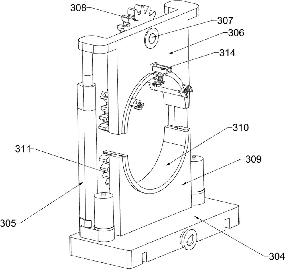
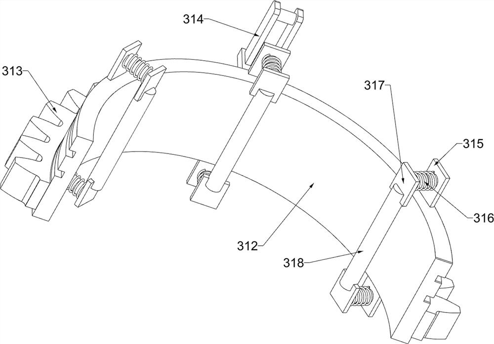
[0032] On the basis of Example 1, according to figure 1 and Figure 3-8As shown, the limit unit includes a first fixed plate 201, a second fixed plate 202, a first guide rail 203, a first electric slider 204, a second guide rail 205, a second electric slider 206, a second fixed frame 207, The first connecting rod 208, the first limiting plate 209 and the first spring 210; two first fixed plates 201 are affixed to the front of the upper surface of the bearing plate 2; two second fixing plates are affixed to the rear of the upper surface of the bearing plate 2 A fixed plate 202; a first guide rail 203 is fixedly connected between the two first fixed plates 201; two first electric sliders 204 are slidably connected to the upper part of the first guide rail 203; There is a second guide rail 205; the upper part of the second guide rail 205 is slidingly connected with two second electric sliders 206; the upper part between the first electric slider 204 and the second electric slide...

Embodiment 3

[0041] On the basis of Example 2, according to figure 1 and Figure 9-11 As shown, a cutting unit is also included; the upper part of the winding unit is connected with a cutting unit; the cutting unit includes a third fixed block 401, a second electric push rod 402, a sliding frame 403, a third fixed frame 404, and a first wedge plate 405 , the second wedge-shaped plate 406, the round rod 407, the cutter 408 and the second spring 409; the upper surface of the first arc-shaped plate 306 is fixedly connected with the third fixed block 401; the third fixed block 401 bottom bolt is connected with the second electric pusher Rod 402; the telescoping part of the second electric push rod 402 is fixedly connected with a sliding frame 403; the upper part of the first arc-shaped plate 306 and is located below the third fixed block 401 is fixedly connected with a third fixed frame 404; the sliding frame 403 and the third fixed The frame 404 is slidingly connected; the upper part of the ...


PUM


Abstract

The invention relates to the field of concrete pipelines, in particular to circumferential steel wire winding equipment for a steel cylinder concrete pipeline. The technical problems are as follows: when a steel wire is wound outside a steel cylinder concrete pipe core, the steel wire is very easy to break, the continuity of the steel wire is reduced, and the steel wire is very easy to loosen after being wound, so that the steel wire is not firmly wound. According to the technical scheme, the circumferential steel wire winding equipment for the steel cylinder concrete pipeline comprises supporting legs, a bearing plate and the like; a bearing plate is fixedly connected to the upper portions of the four supporting legs. The steel cylinder concrete pipe core is limited, the steel cylinder concrete pipe core limiting device can adapt to steel cylinder concrete pipe cores of different sizes, then steel wires are wound on the outer surface of the steel cylinder concrete pipe core, then redundant steel wires are cut off, and then the wound steel wires are rolled, so that the steel wires are tightly attached to the outer portion of the steel cylinder concrete pipe core; breakpoints of the steel wires are avoided, continuity of the steel wires is improved, and loosening of the steel wires after winding is avoided.

Description

technical field [0001] The invention relates to the field of concrete pipelines, in particular to a steel tube concrete pipeline hoop-type winding steel wire equipment. Background technique [0002] At present, in order to improve the strength of steel tubular concrete pipes, steel wires are wound outside the steel tubular concrete core. Breakpoints cause the continuity of the steel wire to decrease, which in turn cannot effectively protect the steel cylinder, resulting in performance defects such as compression resistance and tensile resistance. [0003] To sum up, it is necessary to develop a steel cylinder concrete pipeline hoop winding steel wire equipment to overcome the above problems. Contents of the invention [0004] In order to overcome the shortcoming that when the steel wire is wound outside the concrete tube core of the steel cylinder, it is very easy to cause a break point of the steel wire, resulting in a decrease in the continuity of the steel wire, and at...

Claims


Application Information

Patent Timeline
IPC IPC(8): B21F17/00B21F11/00
CPCB21F17/00B21F11/00Y02P70/10
Inventor 吴充权
Owner 吴充权
Features
  • R&D
  • Intellectual Property
  • Life Sciences
  • Materials
  • Tech Scout
  • Unparalleled Data Quality
  • Higher Quality Content
  • 60% Fewer Hallucinations
Learn More