Automatic steel seal impacting device

An automatic, stencil technology, applied in the field of stencil impact, can solve the problems of unclear printing numbers, inaccurate printing position positioning, etc., to achieve the effect of high practicability, improved printing quality and efficiency, and accurate printing position

Pending Publication Date: 2022-03-25
AVIC SAC COMML AIRCRAFT
View PDF3 Cites 0 Cited by
  • Summary
  • Abstract
  • Description
  • Claims
  • Application Information

AI Technical Summary

Problems solved by technology

[0003] The technical problem to be solved by the present invention is to provide an automatic stamping device for stamping, which can meet the requirements of accurate positioning of the printing area, clear and regular printing numbers, and solve the problems of inaccurate printing position positioning and unclear printing numbers in the prior art. question

Method used


Image

  • Automatic steel seal impacting device
  • Automatic steel seal impacting device
  • Automatic steel seal impacting device

Examples


Embodiment Construction

[0020] The present invention will be further described below in conjunction with the accompanying drawings and embodiments.

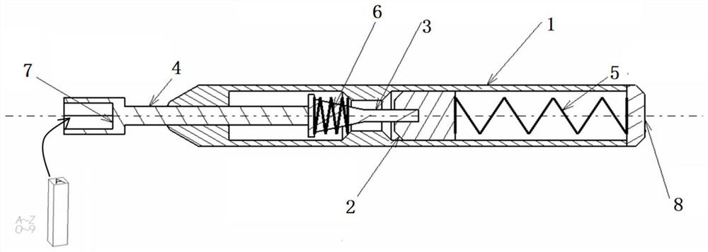
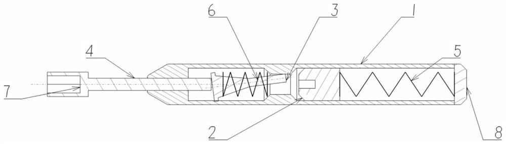
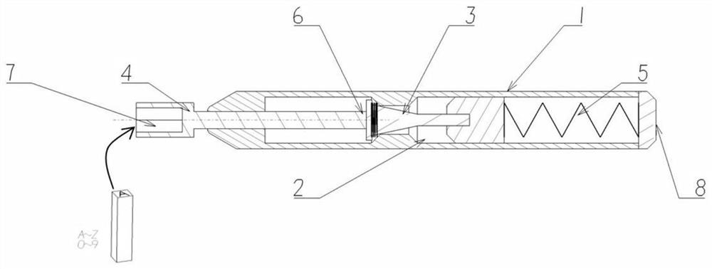
[0021] An automatic impact punching device for stamping, the impact punching device includes a handle 1, a guide groove 2, a guide block 3, an impact rod 4, a compression spring A5, a compression spring B6, a magnetic head 7, and an end cover 8.

[0022] The inside of the handle 1 is a hollow structure, and the middle part of the inner wall is provided with a trapezoidal raised structure, and each of the left and right sides of the raised structure is a chamber; the guide groove 2 is placed in the right chamber inside the handle 1, and the guide groove 2 The middle part of the left end surface is provided with a blind hole, the right end surface of the guide groove 2 is connected with the left end of the compression spring A5, and the right end of the compression spring A5 is connected with the end cover 8. The right end of the handle 1 is provided with...


PUM


Abstract

The invention discloses an automatic steel seal impacting device which comprises a grip, a guide groove, a guide block, an impacting rod, a compression spring, an end cover and a magnetic head, wherein the guide groove, the guide block, the impacting rod and the compression spring are arranged in the grip, the end cover is arranged on the grip, and the magnetic head is connected with the impacting rod. The magnetic head is connected with the impact rod; the steel seal automatic impact device is aligned to a part to be marked and pressed down with force in the direction of a product, the compression spring B is pressed to drive the guide block to move, the guide block slides into a groove opening of the guide groove under stress to drive the guide groove to move, then the compression spring A is pressed to generate reverse impact force, the guide groove and the guide block are reversely pushed to move forwards, and marking is completed. And the impact rod and the magnetic head are driven to move to generate an impact effect and finally finish automatic printing of the steel seal on the surface of the part. The device is simple in principle, compact in structure and convenient to use, and the problems that in an existing method, steel seals are not clear, and printing position positioning is not accurate are solved.

Description

technical field [0001] The invention belongs to the field of stamp impact and relates to a device for printing on the surface of parts. Background technique [0002] At the existing site, the types and quantities of components, tooling, and tools are extremely large and complicated. If the specification allows, the parts and components can be stamped and numbered; the tooling and tools can be marked by marking, which is convenient for on-site identification. At present, most production sites use manual marking. This method has certain defects: 1) The printing depth and character size are not uniform, resulting in unclear and regular numbers; 2) The printing position is not accurately positioned. The automatic stamping device and method for stamping according to the invention can greatly improve the printing quality and efficiency on the surface of parts and components. Contents of the invention [0003] The technical problem to be solved by the present invention is to pr...

Claims


Application Information

Patent Timeline
Patent Type & Authority Applications(China)
IPC IPC(8): B41K1/04B41K1/36
CPCB41K1/04B41K1/36
Inventor 宿小飞孙非朱晨王刚周传文王浩
Owner AVIC SAC COMML AIRCRAFT
Why Eureka
Try Eureka