
Heat transfer printing printer and printing method

A thermal transfer printer and print head technology, applied in transfer printing, rotary printing presses, printing presses, etc., can solve the problems of high printer control accuracy, high manufacturing accuracy requirements, and large printer structure, and achieve compact structure. , the effect of high printing accuracy and low manufacturing cost

Pending Publication Date: 2020-04-03
湖南鼎一致远科技发展股份有限公司
View PDF12 Cites 1 Cited by
  • Summary
  • Abstract
  • Description
  • Claims
  • Application Information

AI Technical Summary

Problems solved by technology

The first type is to set multiple print head assemblies, each print head assembly includes a color ribbon and a print head, and the printing paper passes through multiple print head assemblies in turn to complete multi-color printing. This type of printer has a large structure , the cost is relatively high due to the need to set multiple print head assemblies
The second method is to set up a print head, return the printing paper after printing one color, replace the ribbon and print the second color. The control accuracy is very high, and the printing paper needs to be returned to the same position every time, and the manufacturing accuracy is relatively high, and the repeated paper return is easy to damage the printing paper

Method used


Image

  • Heat transfer printing printer and printing method
  • Heat transfer printing printer and printing method
  • Heat transfer printing printer and printing method

Examples


Embodiment Construction

[0037] The principles and features of the present invention are described below, and the examples given are only used to explain the present invention, and are not intended to limit the scope of the present invention.

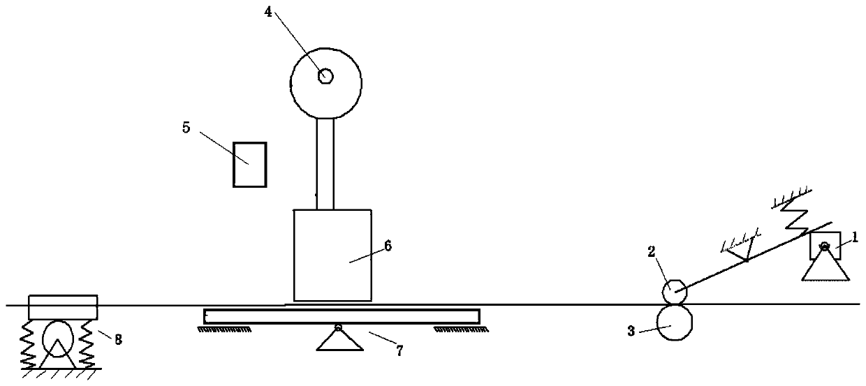
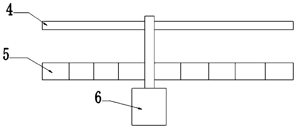
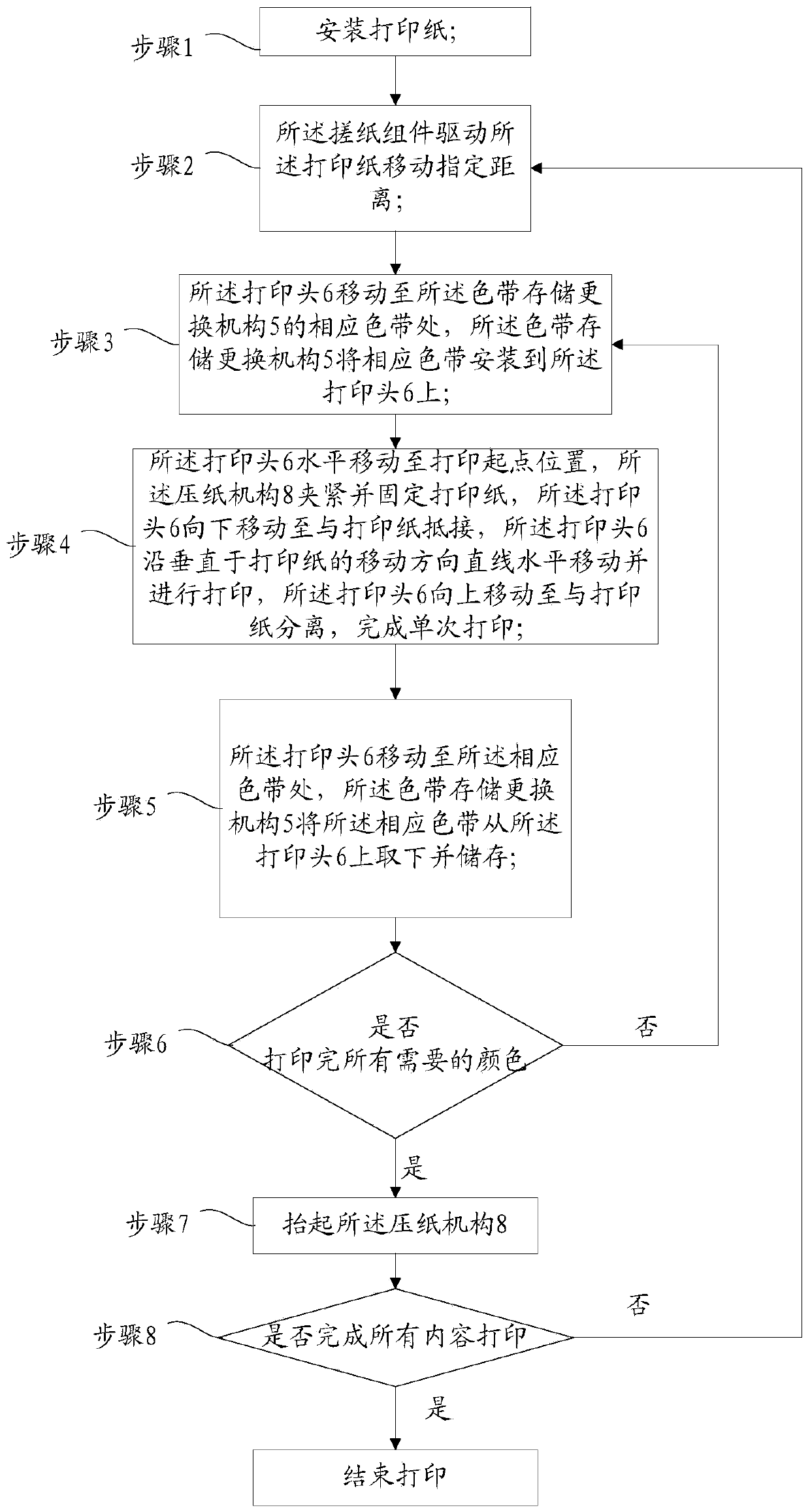
[0038] like figure 1 and figure 2 As shown, this embodiment relates to a thermal transfer printer, including a paper pickup assembly, a print head 6, a ribbon storage and replacement mechanism 5, and a paper pressing mechanism 8. The moving direction of the print head 6 and the ribbon storage and replacement mechanism 5 are installed between the paper pickup assembly and the paper pressing mechanism 8. The print head 6 is located above the printing paper and can be moved along the Horizontal linear reciprocating movement and vertical movement perpendicular to the moving direction of the printing paper, the ribbon storage and replacement mechanism 5 is horizontally arranged perpendicular to the moving direction of the printing paper, and the ribbon storage and...


PUM


Abstract

The invention relates to a heat transfer printing printer and a printing method. The heat transfer printing printer comprises a paper rubbing assembly, a printing head, a colored tape storing and replacing mechanism and a paper pressing mechanism. The paper rubbing assembly and the paper pressing mechanism are successively arranged in the moving direction of printing paper, the printing head and the colored tape storing and replacing mechanism are mounted between the paper rubbing assembly and the paper pressing mechanism, the printing heat is located above the printing paper and can move linearly in a reciprocating manner horizontally in the direction perpendicular to the moving direction of the printing paper and move up and down, the colored tape storing and replacing mechanism is horizontally arranged perpendicular to the moving direction of the printing paper, and the colored tape storing and replacing mechanism is used for storing colored tapes of different colors and replacing the colored tapes to the printing head. The heat transfer printing printer has the beneficial effects that the colored tape storing and replacing mechanism replaces the colored tapes, so that the printing head can print a plurality of colors; the paper rubbing assembly drives the printing paper to move; and the paper pressing mechanism is used for fixing the printing paper when the printing head executes a printing operation to prevent the printing effect from being affected as the printing paper moves. The printer is compact in structure and small in occupied area.

Description

technical field [0001] The invention relates to the field of thermal transfer printers, in particular to a thermal transfer printer and a printing method. Background technique [0002] Thermal transfer printing technology is the product of the combination of heat transfer principle and hot stamping (hot stamp) technology. Among the thermal transfer barcode printers manufactured according to this technology, the most common one is the "melting type" thermal transfer printer. It is the most commonly used industrial printer, which uses polyester film as the base band of the ribbon, and the surface layer is coated with waxy solid ink. When printing, the microprocessor controls the heating of the heating element in the thermal (sensitive) printing head, so that the hot-melt ink layer on the film ribbon is melted, and then transferred to ordinary paper to generate long-term retention graphics. Because the film ribbon overcomes the mesh structure of fabric ribbons commonly used in...

Claims


Application Information

Patent Timeline
Patent Type & Authority Applications(China)
IPC IPC(8): B41F16/00B41J2/325B41J3/407B41J11/00B41J15/16
CPCB41J3/407B41J11/00B41J11/0045B41J11/006B41J15/16B41J2/325B41F16/00
Inventor 李留祥唐国初
Owner 湖南鼎一致远科技发展股份有限公司
Learn More