Wall body supporting equipment for assembly type building installation

A support equipment and assembly technology, which is applied in the processing of building materials, construction, building construction, etc., can solve the problems of small stress point area, unstable wall structure, and no wall support, etc., to achieve The support structure is stable, easy to disassemble quickly, and the effect of eliminating height errors

Active Publication Date: 2022-03-25
成都建工第三建筑工程有限公司
View PDF4 Cites 0 Cited by
  • Summary
  • Abstract
  • Description
  • Claims
  • Application Information

AI Technical Summary

Problems solved by technology

[0003] However, due to the wedge-shaped structure of the wooden wedge, there are many problems. For example, the area of ​​the force-bearing point at the bottom of the wall is small, which leads to the unstable force of the wall structure, and the joint between the ceiling and the ceiling is not tight. There is no support for the wall, and before hitting the wooden wedge, it is necessary to choose a suitable wooden wedge according to the size of the gap. Usually, a larger one is used to form an effective support, which causes the wooden wedge to be squeezed after being struck. Difficulty with subsequent removal of wooden wedges

Method used


Image

  • Wall body supporting equipment for assembly type building installation
  • Wall body supporting equipment for assembly type building installation
  • Wall body supporting equipment for assembly type building installation

Examples


Embodiment Construction

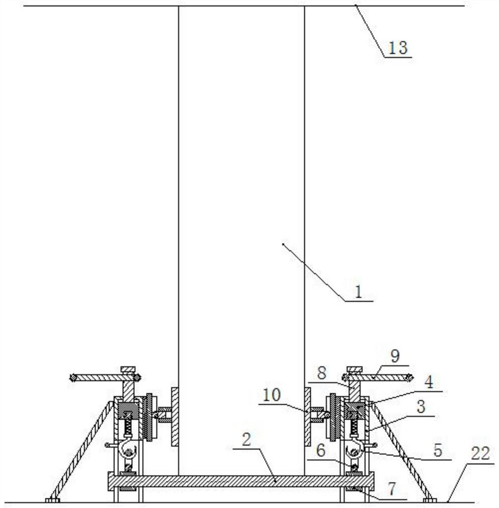
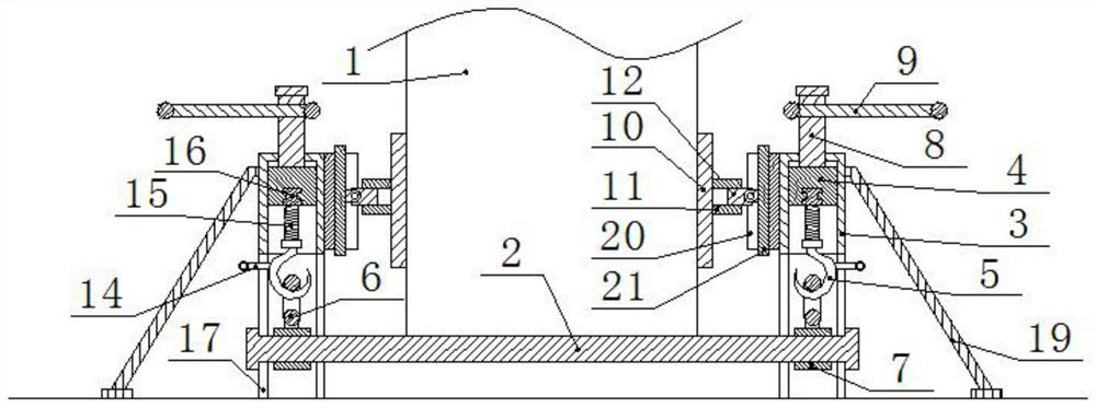
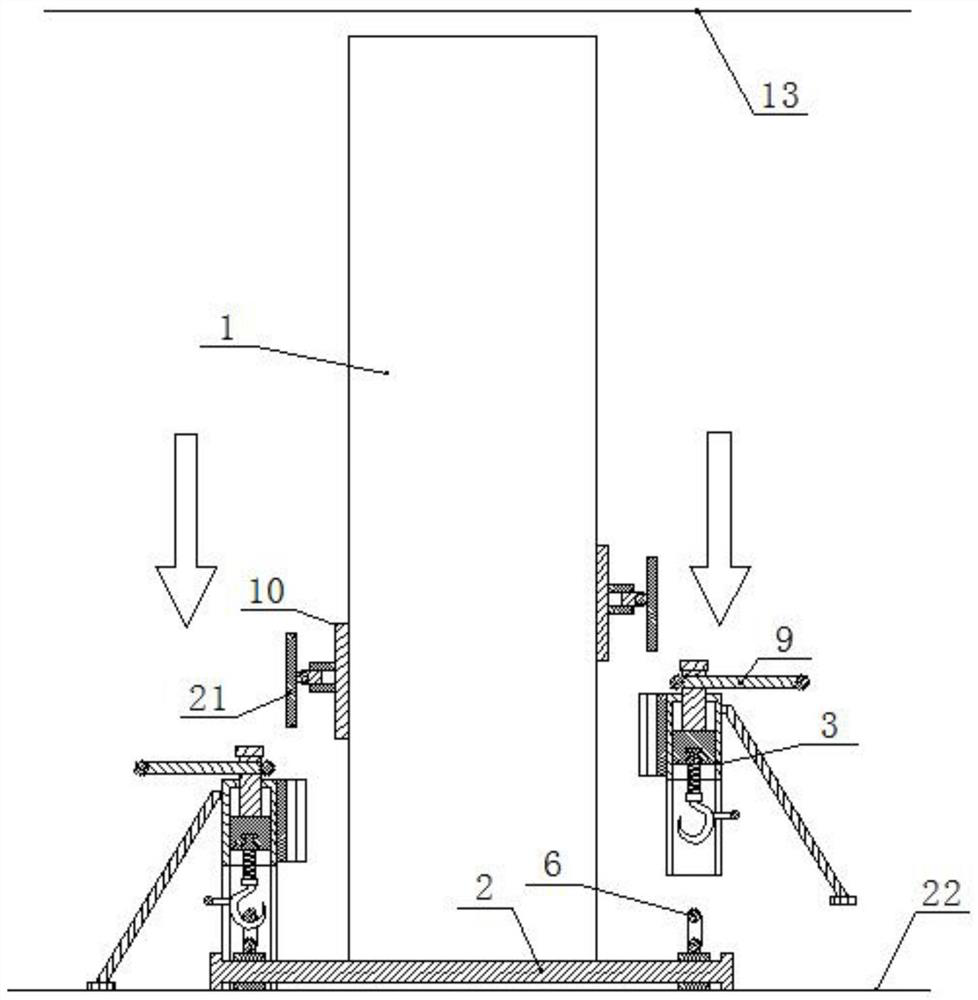
[0029] Below will combine the appended in the embodiment of the present invention Figure 1-9 , clearly and completely describe the technical solutions in the embodiments of the present invention, obviously, the described embodiments are only some embodiments of the present invention, not all embodiments. Unless otherwise specified, the technical means used in the embodiments are conventional means well known to those skilled in the art.

[0030] In describing the present invention, it should be understood that the terms "longitudinal", "transverse", "upper", "lower", "front", "rear", "left", "right", "vertical", The orientations or positional relationships indicated by "horizontal", "top", "bottom", "inner", "outer", etc. are based on the orientations or positional relationships shown in the drawings, and are only for the convenience of describing the present invention, rather than indicating or It should not be construed as limiting the invention by implying that a referenc...


PUM


Abstract

The invention belongs to the field of fabricated buildings, and particularly provides a wall supporting device for fabricated building installation, which comprises at least two supporting assemblies arranged side by side and parallel to each other; the supporting assembly comprises a supporting rod, the supporting rod is arranged below a wall and abuts against the wall, two symmetrically-arranged hoisting mechanisms are arranged at the two ends of the supporting rod, each hoisting mechanism comprises a shell, a bearing block is arranged in each shell in an up-down sliding mode and connected with the supporting rod, and the supporting rod is connected with the supporting rod. And a driving mechanism used for pushing the bearing block to slide and limiting is further arranged in the shell, and the beneficial effects that the wall body can be effectively supported to be tightly attached to the ceiling, and effective horizontal supporting is formed are achieved.

Description

technical field [0001] The invention belongs to the field of prefabricated buildings, and in particular relates to the structural improvement of wall support equipment used for the installation of prefabricated buildings. Background technique [0002] Prefabricated buildings refer to buildings assembled and installed on site through reliable connections, such as various types of non-load-bearing walls installed indoors, including partition walls, etc. Multiple walls are placed vertically in a row to form a non-load-bearing assembly Type wall structure, when installing this type of wall in the prior art, such as Figure 9 As shown, the length of the wall usually does not match the height of the ceiling, and a certain gap is reserved for the installation of the wall. During installation, the bottom of the wall is often lifted up by wooden wedges to form a supporting structure. The wooden wedges are used in specific construction. When it is used, it is usually hammered into the...

Claims


Application Information

Patent Timeline
Patent Type & Authority Applications(China)
IPC IPC(8): E04G21/26
CPCE04G21/26
Inventor 夏葵凌书黄尚珩
Owner 成都建工第三建筑工程有限公司
Why Eureka
Try Eureka