Arrangement for automatic parking brake system

A braking system, automatic technology, applied in the direction of braking safety system, braking transmission device, brake, etc., can solve the problems of expensive device structure, complex infrastructure, complex and other problems, and achieve the effect of cost increase

Pending Publication Date: 2022-03-29
ROBERT BOSCH GMBH
View PDF1 Cites 0 Cited by
  • Summary
  • Abstract
  • Description
  • Claims
  • Application Information

AI Technical Summary

Problems solved by technology

[0004] Disadvantages of the solutions known from the prior art, in particular complex infrastructure and complex and expensive plant construction

Method used


Image

  • Arrangement for automatic parking brake system
  • Arrangement for automatic parking brake system
  • Arrangement for automatic parking brake system

Examples


Embodiment Construction

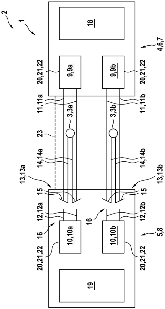
[0045] The device 1 according to the invention for actuating an automatic parking brake system, as exemplified in figure 1 with 2 is generally part of a motor vehicle 2 that includes a parking brake system, not shown otherwise. At least one actuator 3 of a parking brake system is actuated by means of the device 1 , wherein the actuator 3 actuates at least one associated parking brake (not shown) of the parking brake system. In the exemplary embodiment shown, the device 1 has two actuators 3 of an automatic parking brake system, a first actuator 3 a for actuating the first parking brake and a second actuator 3 a for actuating the first parking brake. Second actuator 3b of the parking brake. The device 1 has two associated control units 9 , 10 for the respective actuator 3 , which are used to control the associated actuator 3 in each case. In the exemplary embodiment shown, the device 1 has at least one controller 4 , 5 for actuating at least one actuator 3 and thus at least ...


PUM


Abstract

The invention relates to a device (1) for actuating an actuator (3) of an automatic parking brake system of a motor vehicle (2), the device (1) having a switching mechanism (13) associated with the actuator (3), which switching mechanism enables selective actuation of the actuator (3) by means of one of two associated control units (9, 10). The invention also relates to a method for operating such a device (1).

Description

technical field [0001] The invention relates to a device for actuating at least one actuator of an automatic parking brake system of a motor vehicle. The invention also relates to a method for operating such a device. Background technique [0002] The use of automatic parking brake systems in motor vehicles is well known. Such a parking brake system serves the purpose of immobilizing the associated motor vehicle when necessary, especially in a parking position, and of preventing the motor vehicle from rolling. For this purpose, the parking brake system usually has a parking brake, also called a parking brake, which can be actuated, ie fixed and released, by means of a corresponding actuator. The parking brake system is usually operated by means of a device with a controller. The controller, also called brake controller, controls the actuator for actuating the parking brake. During the operation of the motor vehicle, in particular of the device, functional defects or even...

Claims


Application Information

Patent Timeline
Patent Type & Authority Applications(China)
IPC IPC(8): B60T13/74B60T17/18
CPCB60T13/748B60T17/18B60T13/74B60T17/22
Inventor F·贝尔勒-米勒T·普策
Owner ROBERT BOSCH GMBH
Why Eureka
Try Eureka