Coating machine

A coating machine and driving mechanism technology, applied in the field of coating machines, can solve problems such as inconvenient operation, and achieve the effect of convenient operation and simple structure

Pending Publication Date: 2022-04-01
惠州市新鑫辉自动化设备有限公司
View PDF12 Cites 0 Cited by
  • Summary
  • Abstract
  • Description
  • Claims
  • Application Information

AI Technical Summary

Problems solved by technology

When the coating process of the coating machine changes, it may only need one unwinding roller to rotate to drive the material belt, while the other unwinding roller does not need to rotate. At this time, it is necessary to disconnect the other unwinding roller from the driving source. Connection, in the prior art, it often needs to be removed manually, which is very inconvenient to operate

Method used


Image

  • Coating machine
  • Coating machine
  • Coating machine

Examples


Embodiment Construction

[0042] The present invention will be further described in detail below in conjunction with the accompanying drawings and embodiments. It should be understood that the specific embodiments described here are only used to explain the present invention, but not to limit the present invention. In addition, it should be noted that, for the convenience of description, only some structures related to the present invention are shown in the drawings but not all structures.

[0043] In the description of the present invention, unless otherwise clearly specified and limited, the terms "connected", "connected" and "fixed" should be understood in a broad sense, for example, it can be a fixed connection, a detachable connection, or an integrated ; It can be a mechanical connection or an electrical connection; it can be a direct connection or an indirect connection through an intermediary, and it can be the internal communication of two components or the interaction relationship between two ...


PUM


Abstract

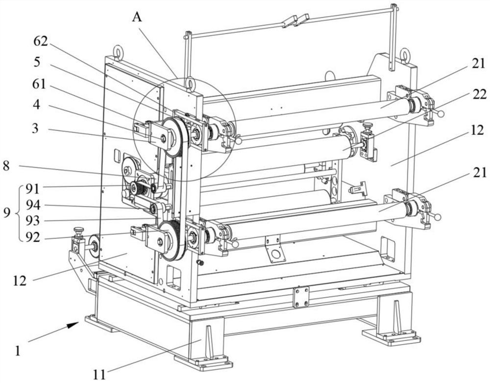
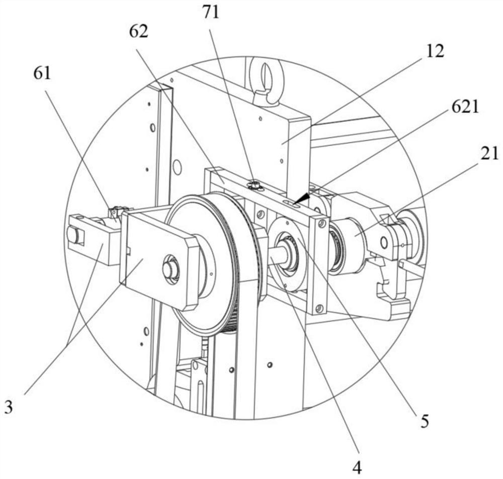
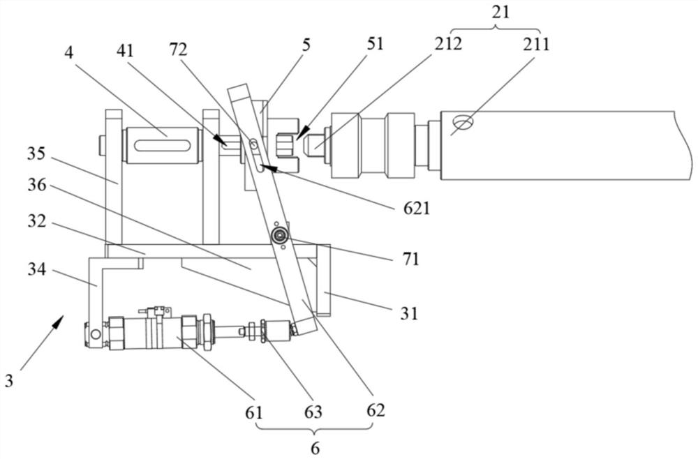
The invention relates to the technical field of coating equipment, and discloses a coating machine. The coating machine comprises a frame body, an unwinding roller rotatably arranged on the frame body and a driving source used for driving the unwinding roller to rotate, and further comprises a supporting assembly, a transmission shaft, a connecting shaft sleeve and a driving mechanism, the supporting assembly is arranged on one side of the frame body, the transmission shaft is rotatably arranged on the supporting assembly, one end of the transmission shaft is connected with the driving source, and the other end of the transmission shaft is connected with the driving source. The connecting shaft sleeve is connected with the other end of the transmission shaft so as to rotate synchronously with the transmission shaft, the connecting shaft sleeve can slide in the axial direction of the transmission shaft, a clamping groove is formed in the end of the connecting shaft sleeve, the driving mechanism is arranged on the supporting assembly, the output end of the driving mechanism is movably connected with the connecting shaft sleeve, and the driving mechanism can drive the connecting shaft sleeve to slide along the transmission shaft. And the clamping groove can be clamped with or separated from the end part of the unwinding roller. According to the coating machine, the driving state of the driving source to the unwinding roller is conveniently and flexibly set, different coating process requirements are met, manual disassembly and assembly are not needed, the structure is simple, and operation is convenient.

Description

technical field [0001] The invention relates to the technical field of coating equipment, in particular to a coating machine. Background technique [0002] The coating machine is a device that can coat the positive / negative electrode slurry of the battery on the current collector (material strip) to form the battery pole sheet. The coating machine generally uses a driving source to drive the unwinding roller to rotate, so that the unwinding roller drives the material belt to move in a preset direction. In order to save the number of driving sources, in some cases the two unwinding rollers of the coating machine are driven by the same driving source. When the coating process of the coating machine changes, it may only need one unwinding roller to rotate to drive the material belt, while the other unwinding roller does not need to rotate. At this time, it is necessary to disconnect the other unwinding roller from the driving source. The connection, in the prior art, often ne...

Claims


Application Information

Patent Timeline
Patent Type & Authority Applications(China)
IPC IPC(8): B65H16/10B65H16/02
Inventor 叶鑫林李世成刘路云
Owner 惠州市新鑫辉自动化设备有限公司
Why Eureka
Try Eureka