
A W-band waveguide bandpass filter

A bandpass filter and waveguide technology, which is applied in waveguide devices, sustainable communication technology, advanced technology, etc., can solve the problems such as the filter square coefficient is not prominent, the stop band suppression degree is limited, and the filter structure is complicated. Achieve the effects of low processing difficulty, low insertion loss, good design freedom and filtering characteristics

Active Publication Date: 2022-07-12
XI AN JIAOTONG UNIV
View PDF8 Cites 0 Cited by
  • Summary
  • Abstract
  • Description
  • Claims
  • Application Information

AI Technical Summary

Problems solved by technology

The technical solutions disclosed above have flexible bandwidth adjustment capabilities and good insertion loss characteristics; however, they are all based on the microstrip resonator structure of the dielectric substrate to introduce transmission zeros to achieve the out-of-band suppression characteristics of the filter. Multiple resonators will lead to the complex structure of the filter itself and it is difficult to analyze; at the same time, the stop-band suppression based on the introduction of transmission zeros is limited and the filter square coefficient is not outstanding, which is difficult to meet the current specific high stop-band suppression application scenarios Requirements (exemplary, such as noise suppression in the field of electronic compatibility, etc.)

Method used


Image

  • A W-band waveguide bandpass filter
  • A W-band waveguide bandpass filter
  • A W-band waveguide bandpass filter

Examples


Embodiment Construction

[0036] In order to make those skilled in the art better understand the solutions of the present invention, the technical solutions in the embodiments of the present invention will be clearly and completely described below with reference to the accompanying drawings in the embodiments of the present invention. Obviously, the described embodiments are only Embodiments are part of the present invention, but not all embodiments. Based on the embodiments of the present invention, all other embodiments obtained by persons of ordinary skill in the art without creative efforts shall fall within the protection scope of the present invention.

[0037]It should be noted that the terms "first", "second" and the like in the description and claims of the present invention and the above drawings are used to distinguish similar objects, and are not necessarily used to describe a specific sequence or sequence. It is to be understood that the data so used may be interchanged under appropriate c...


PUM

PropertyMeasurementUnit
thicknessaaaaaaaaaa
dielectric lossaaaaaaaaaa

Abstract

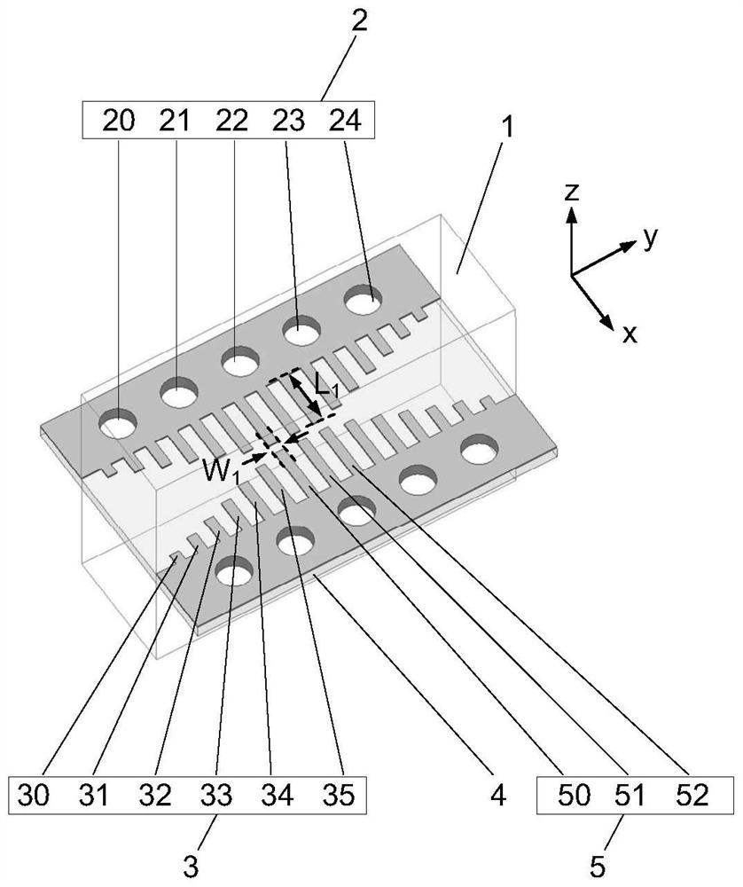
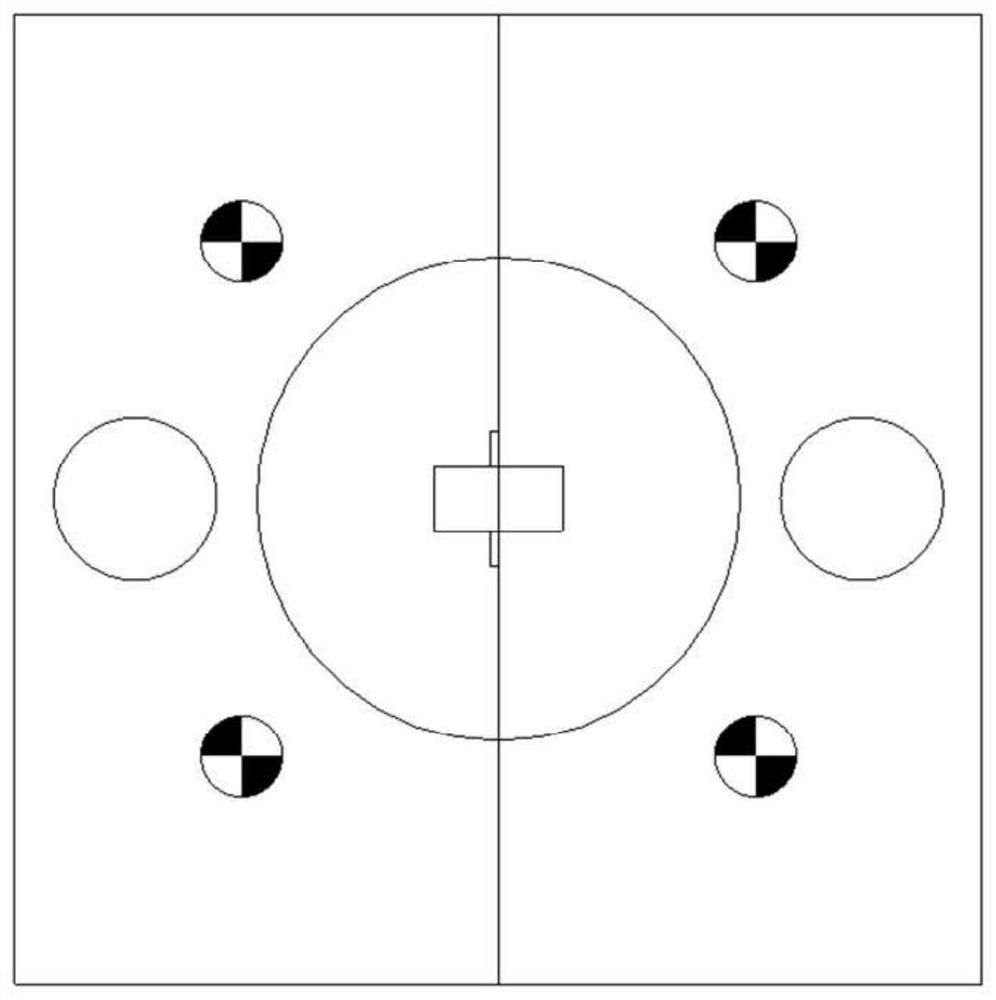
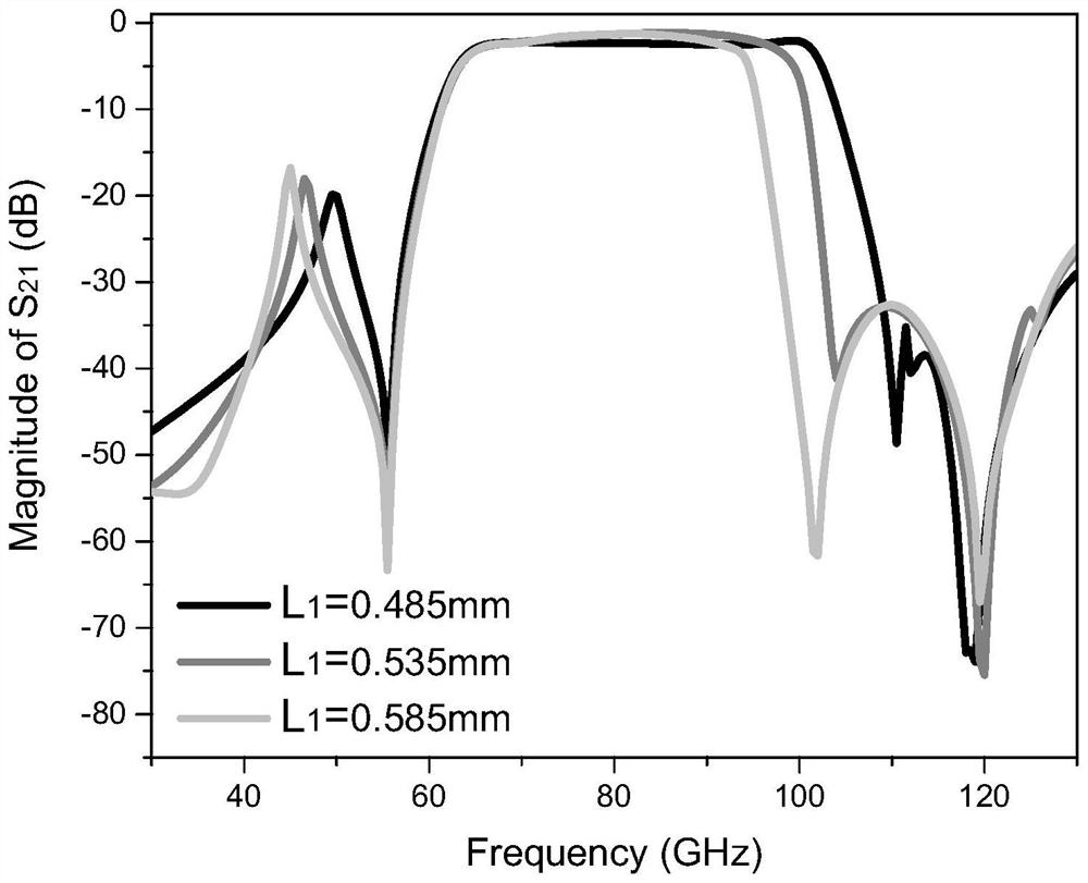
The invention discloses a W-band waveguide bandpass filter, comprising: a waveguide and a dielectric substrate fixedly arranged in the waveguide; the dielectric substrate is partially arranged in the inner cavity of the waveguide; the dielectric substrate is arranged in the inner cavity of the waveguide; The part in the inner cavity of the waveguide is sequentially provided with an input transition rectangular metal strip, a periodic rectangular metal strip and an output transition rectangular metal strip along the preset millimeter wave signal propagation direction; the dielectric substrate is arranged on the The portion of the waveguide outside the cavity is provided with a radio frequency ground. The invention specifically provides a W-band dielectric substrate waveguide bandpass filter, which has high stopband suppression characteristics, good square coefficient, low insertion loss, wide operating bandwidth and flexible passband adjustment characteristics, which can meet the requirements of modern communication in specific scenarios. need.

Description

technical field [0001] The invention belongs to the technical field of millimeter wave filters, in particular to a W-band waveguide bandpass filter. Background technique [0002] In recent years, with the rapid development of microwave communication technology in the military and civilian fields, spectrum resources have become increasingly tight, especially in the field of civilian mobile communications, where spectrum resources are close to saturation. Technology to achieve high-quality communication has become a key research topic. In millimeter-wave communication, in order to increase the utilization rate of high-frequency spectrum resources and avoid mutual interference between microwave and millimeter-wave systems and between millimeter-wave systems as much as possible, millimeter-wave filters with frequency selection characteristics have become the goal to achieve this. core device. Millimeter wave communication has the advantages of good directivity, large communica...

Claims


Application Information

Patent Timeline
Patent Type & Authority Patents(China)
IPC IPC(8): H01P1/203
CPCY02D30/70
Inventor 徐开达刘逸群李建星张安学
Owner XI AN JIAOTONG UNIV
Learn More