Connector assembly

A technology of electrical connectors and molded parts, applied in the field of input/output connectors, can solve problems such as increasing crosstalk of connectors

Pending Publication Date: 2022-04-01
MOLEX INC
View PDF0 Cites 0 Cited by
  • Summary
  • Abstract
  • Description
  • Claims
  • Application Information

AI Technical Summary

Problems solved by technology

However, if space is an issue, then it is desirable to reduce the pitch of the connectors and bring all terminals closer together (this increases crosstalk)

Method used


Image

  • Connector assembly
  • Connector assembly
  • Connector assembly

Examples


Embodiment Construction

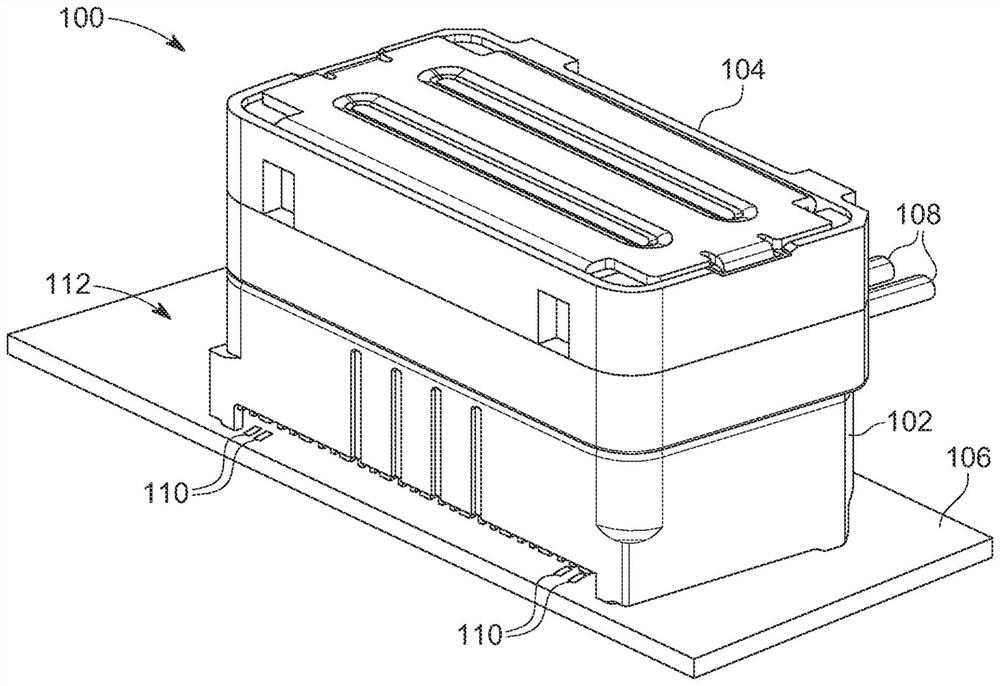
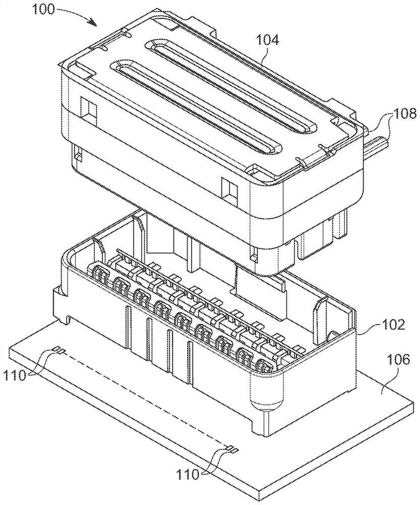
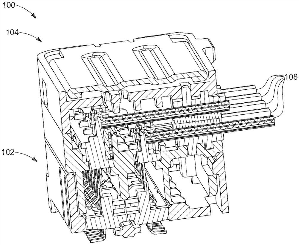
[0052] refer to Figure 1 to Figure 4 , shows a wire-to-board connector assembly 100 . The connector assembly 100 includes a plug connector 102 and a receptacle connector 104 . The plug connector 102 is configured to be mounted on a substrate 106 and the receptacle connector 104 is configured to be terminated to a plurality of conductive cables 108 . Plug connector 102 can mate with receptacle connector 104 to establish electrical communication between substrate 106 and plurality of conductive cables 108 . Plug connector 102 can be placed against a surface of substrate 106, while receptacle connector 104 can be arranged so that cable 108 is parallel to the substrate and generally perpendicular to the mating or stacking direction of plug connector 102 and receptacle connector 104, connecting The converter assembly 100 thus has an orthogonal configuration. Furthermore, the vertical height of the header connector 102 and the receptacle connector 104 can be minimized so that th...


PUM


Abstract

An electrical connector assembly may include a plug connector and a receptacle connector that can be docked together. Conductive communication between the plug connector and the receptacle connector is established by docking signal terminals and ground terminals contained in terminal assemblies housed in the connectors. In order to align and support the signal and ground terminals, the terminal may be part of a terminal sheet and the terminal subassembly may be assembled from more than one sheet. The terminal sheet may include ground features that improve electrical characteristics and data transfer through the electrical connector assembly.

Description

[0001] related application [0002] This application claims priority to US Provisional Application US62 / 897006, filed September 6, 2019, which is hereby incorporated by reference in its entirety. technical field [0003] The present disclosure relates generally to electrical connectors, and more particularly to input / output connectors suitable for use in high data rate applications. Background technique [0004] Input / Output (IO) connectors can be designed for a variety of systems, including board-to-board systems, wire-to-wire-to-board systems, and wire-to-board systems. The wire-to-board system includes a free-end connector attached to a wire and a fixed-end connector attached to a substrate. There are a wide range of suitable many designs for each type of system, depending on the requirements and the environment in which the connector is intended to be used. [0005] However, for applications with high data rates and limited physical space, many competing requirements m...

Claims


Application Information

Patent Timeline
Patent Type & Authority Applications(China)
IPC IPC(8): H01R13/02H01R13/40H01R13/648
CPCH01R12/79H01R12/716H01R13/405H01R13/6594H01R43/205H01R13/506H01R13/6597H01R13/6585H01R13/6471H01R12/707H01R12/75
Inventor 约翰·C·劳尔克斯罗纳德·布拉德贝利乔伊·法雅奥古斯塔·P·潘尼拉丹尼尔·B·麦葛文
Owner MOLEX INC
Why Eureka
Try Eureka