
Hanging hook dangling limiting mechanism of bridge crane

A technology of bridge crane and limit mechanism, which is applied in the direction of load hanging components, transportation and packaging, etc. It can solve the problems of reducing the safety of lifting and transportation, and achieve the effect of preventing suspension, preventing swing and improving safety

Inactive Publication Date: 2022-04-05
江苏博鸿起重机械有限公司
View PDF0 Cites 0 Cited by
  • Summary
  • Abstract
  • Description
  • Claims
  • Application Information

AI Technical Summary

Problems solved by technology

The bridge frame of the bridge crane runs longitudinally along the rails laid on the elevated sides on both sides, and the hoisting trolley runs horizontally along the rails laid on the bridge frame, forming a rectangular working range, which can make full use of the space under the bridge frame for hoisting and transporting materials. Hindered by ground equipment, this kind of crane is widely used in indoor and outdoor warehouses, workshops, docks and open-air storage yards. When lifting objects, under the action of inertia, the heavy objects will run one step slower than the lifting trolley , when the lifting trolley stops, the weight will rush forward again, which will cause the weight to swing and reduce the safety of lifting. However, the existing bridge cranes cannot solve the above problems. Therefore, the present invention proposes a Hook Suspension Limit Mechanism of Bridge Crane

Method used


Image

  • Hanging hook dangling limiting mechanism of bridge crane
  • Hanging hook dangling limiting mechanism of bridge crane
  • Hanging hook dangling limiting mechanism of bridge crane

Examples


Embodiment approach

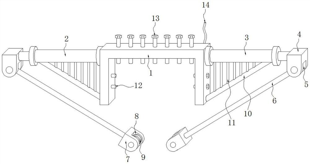
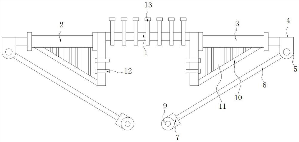
[0020] As a preferred embodiment of the present invention, an inclined support rod 10 is fixedly installed between one end of the left electric push rod 2 and the right electric push rod 3 and the bottom of the fixed frame 1, and the left electric push rod 2 and Several support vertical bars 11 are fixedly installed between the right electric push rod 3 and the inclined support bar 10 .

[0021] As a preferred embodiment of the present invention, both sides of the fixing frame 1 are fitted with fixing bolts 12 through external threads and internal threads.

[0022] As a preferred embodiment of the present invention, the fixed frame 1 is connected with a power cord 14 , and the power cord 14 is electrically connected with the left electric push rod 2 and the right electric push rod 3 .

[0023] As a preferred embodiment of the present invention, the number of the adjusting bolts 13 is seven.

[0024] As a preferred embodiment of the present invention, when in use, the fixed fr...


PUM


Abstract

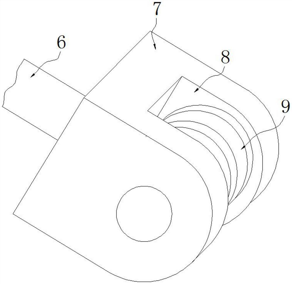
The invention provides a bridge crane hook dangling limiting mechanism which comprises a fixing frame, a left electric push rod and a right electric push rod, and the left electric push rod and the right electric push rod are fixedly installed on the two sides of the top of the fixing frame respectively. A left electric push rod and a right electric push rod are installed on the two sides of the fixing frame correspondingly, dragging rods are installed on output shafts of the left electric push rod and the right electric push rod correspondingly, and when the crane carriage moves forwards, the left electric push rod located on the rear portion stretches, so that a lifting rope on the rear portion is pulled by dragging a limiting base, and the lifting rope is lifted. And similarly, when the hoisting trolley stops, the right electric push rod in the front extends, so that the hoisting hook and the heavy object have the trend of moving backwards, the impulsive force brought by inertia of the heavy object is counteracted, and dangling can be effectively prevented. And the use safety is improved.

Description

technical field [0001] The invention belongs to the technical field of crane accessories, and in particular relates to a suspension hook suspension limit mechanism of a bridge crane. Background technique [0002] A bridge-type crane whose bridge runs on elevated tracks, also known as a crane. The bridge frame of the bridge crane runs longitudinally along the rails laid on the elevated sides on both sides, and the hoisting trolley runs horizontally along the rails laid on the bridge frame, forming a rectangular working range, which can make full use of the space under the bridge frame for hoisting and transporting materials. Hindered by ground equipment, this kind of crane is widely used in indoor and outdoor warehouses, workshops, docks and open-air storage yards. When lifting objects, under the action of inertia, the heavy objects will run one step slower than the lifting trolley , when the lifting trolley stops, the weight will rush forward again, which will cause the wei...

Claims


Application Information

Patent Timeline
Patent Type & Authority Applications(China)
IPC IPC(8): B66C13/06
Inventor 郑小燕
Owner 江苏博鸿起重机械有限公司
Learn More