Gear pulse type cutting device in drive axle and cutting process thereof
A cutting device and pulse-type technology, applied in gear tooth manufacturing devices, belts/chains/gears, gear teeth, etc., can solve the problems of cutting fluid waste, poor working environment for employees, and increased hobbing costs, so as to reduce costs, The effect of reducing waste and reducing pollution
- Summary
- Abstract
- Description
- Claims
- Application Information
AI Technical Summary
Problems solved by technology
Method used
Image
Examples
Embodiment 1
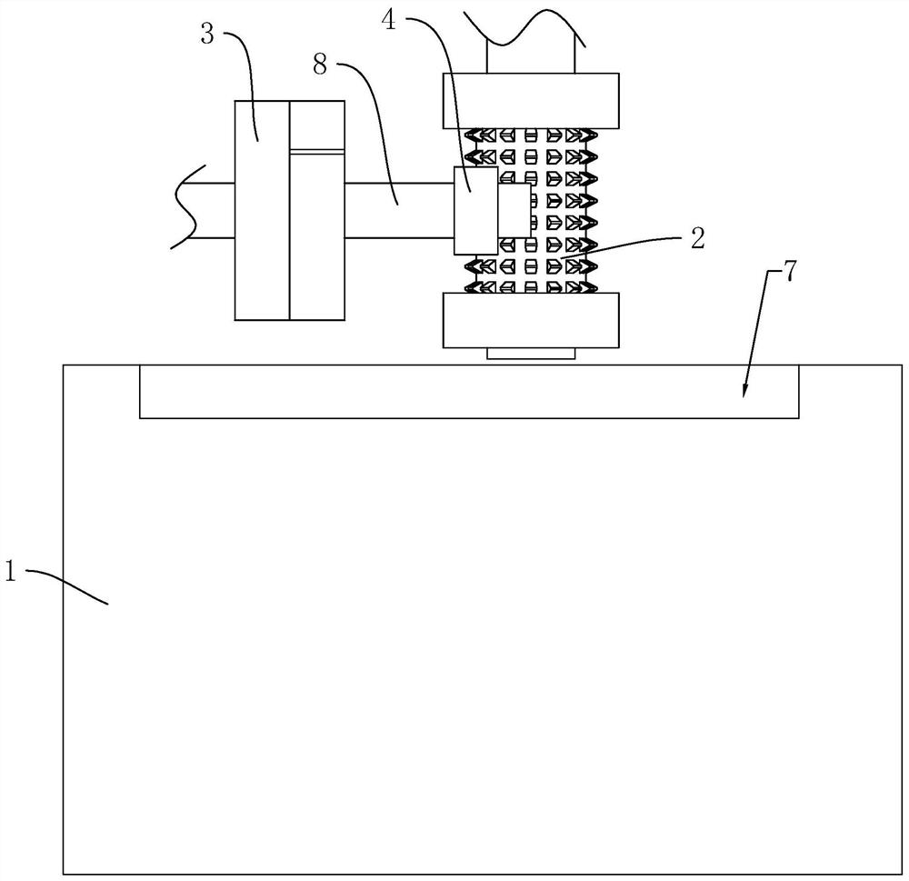
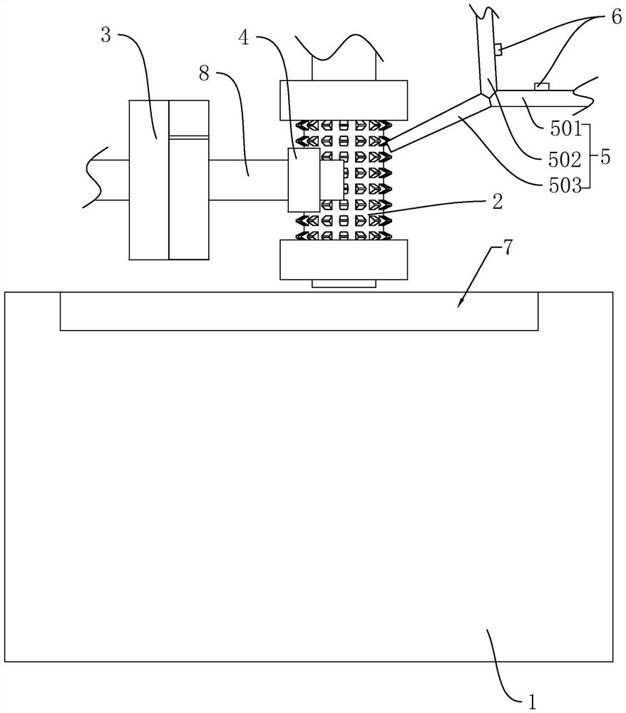
[0040] A gear pulse type cutting device in a drive axle, refer to figure 2 , including a machine 1, the machine 1 is provided with a hob 2 and a chuck 3 whose axes are perpendicular to each other, the gear base 4 to be cut is clamped in the chuck 3 through an integrally formed shaft 8, and the machine 1 and A cutting fluid recovery tank 7 is arranged at the bottom of the hob 2 . During the cutting process, the hob 2 rotates at a high speed, while the gear base 4 rotates slowly under the drive of the chuck 3 and moves horizontally toward the hob 2, so that the two contact and roll out of the tooth hole.
[0041]The cutting device also includes a three-way pipe 5 , and the three-way pipe 5 includes a liquid feed pipe 501 , a gas feed pipe 502 and a pulse discharge pipe 503 that communicate with each other. During the cutting process, the liquid feed pipe 501 is used to deliver the cutting fluid to the pulse discharge pipe 503; one end of the gas feed pipe 502 communicates with...
Embodiment 2
[0050] A gear pulse cutting process in the drive axle, the difference from Embodiment 1 is: the time for each cutting fluid to be ejected from the pulse discharge pipe 503 is set to 100ms; each time the compressed air is ejected from the pulse The ejection time of the discharge pipe 503 is all set to be 60ms.
Embodiment 3
[0052] A kind of gear pulse type cutting device in drive axle, refer to figure 2 , including a machine 1, the machine 1 is provided with a hob 2 and a chuck 3 whose axes are perpendicular to each other, the gear base 4 to be cut is clamped in the chuck 3 through an integrally formed shaft 8, and the machine 1 and A cutting fluid recovery tank 7 is arranged at the bottom of the hob 2 . During the cutting process, the hob 2 rotates at a high speed, while the gear base 4 rotates slowly under the drive of the chuck 3 and moves horizontally toward the hob 2, so that the two contact and roll out of the tooth hole.
[0053] The cutting device also includes a three-way pipe 5 , and the three-way pipe 5 includes a liquid feed pipe 501 , a gas feed pipe 502 and a pulse discharge pipe 503 that communicate with each other. During the cutting process, the liquid feed pipe 501 is used to deliver the cutting fluid to the pulse discharge pipe 503; one end of the gas feed pipe 502 communicat...
PUM
 Abstract
Description
Claims
Application Information
 - R&D
- Intellectual Property
- Life Sciences
- Materials
- Tech Scout
- Unparalleled Data Quality
- Higher Quality Content
- 60% Fewer Hallucinations
Browse by: Latest US Patents, China's latest patents, Technical Efficacy Thesaurus, Application Domain, Technology Topic, Popular Technical Reports.
© 2025 PatSnap. All rights reserved.Legal|Privacy policy|Modern Slavery Act Transparency Statement|Sitemap|About US| Contact US: help@patsnap.com


