Scrubber air duct and sewage tank integrated structure

A waste water tank and washing machine technology, which is applied in the integrated structure of the washing machine's air duct and sewage tank, can solve the problems of poor positioning reliability, increased body weight, and fan damage, and achieves the effect of convenient cleaning and stable use

Pending Publication Date: 2022-04-12
江苏上菱生活电器有限公司
View PDF0 Cites 0 Cited by
  • Summary
  • Abstract
  • Description
  • Claims
  • Application Information

AI Technical Summary

Problems solved by technology

[0003] In the existing structure, because the sewage tank is on the fuselage, the structure is similar to a cylindrical water tank. The traditionally connected suction duct will suck the sewage into the fan at the same time during the suction and cause damage to the fan, which is not conducive to the stability of the equipment. In addition, the existing air duct structure usually uses a bead positioning and unlocking device during installation, which has problems such as poor positioning reliability, large unlocking torque

Method used


Image

  • Scrubber air duct and sewage tank integrated structure
  • Scrubber air duct and sewage tank integrated structure
  • Scrubber air duct and sewage tank integrated structure

Examples


Example Embodiment

[0029] Example 1

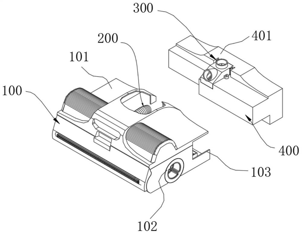
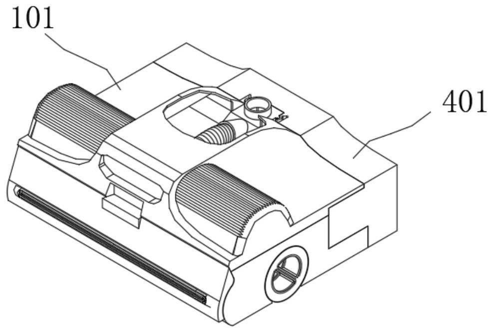
[0030] refer to Figure 1-7 , which is the first embodiment of the present invention, provides an integrated structure of the air duct and sewage tank of the scrubber, including: the scrubber assembly 100, the suction assembly 200, the air duct assembly 300 and the sewage tank assembly 400, the scrubber The machine assembly 100 includes an upper cover 101 , a washing machine body 102 and a chassis 103 , the upper cover 101 is correspondingly connected to the upper side of the washing machine body 102 , and the chassis 103 is correspondingly connected to the lower end of the washing machine body 102 .

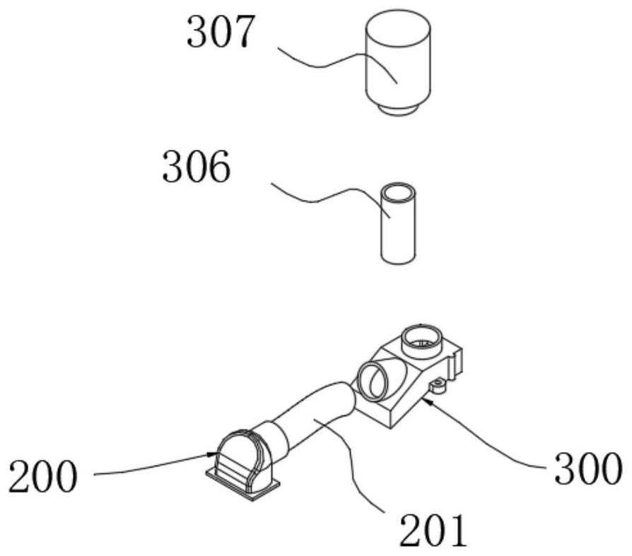
[0031] Wherein, the air suction assembly 200 includes a first air suction duct 201 connected to the washing machine body 102. Specifically, the side wall of the first air suction duct is connected with a mounting seat communicating with it, and the outer wall of the mounting seat is provided with The mounting plate is fixedly connected with the external groun...

Example Embodiment

[0037] Example 2

[0038] refer to Figure 1-7 , which is the second embodiment of the present invention. This embodiment is different from the first embodiment in that: the upper cover 101 is connected to the upper end of the washing machine body 102 by buckling, and the chassis 103 is fixedly connected to the washing machine body 102 by a plurality of bolts. The lower end of the floor washing machine body 102 is provided with a rolling brush inside the floor washing machine body 102, and the lower end of the rolling brush extends to the lower side of the chassis 103 and contacts the ground.

[0039] Compared with Embodiment 1, further, the side wall of the sewage tank body 401 away from the housing 402 is provided with a sewage outlet communicating with the inside thereof, and the outside of the sewage tank body 401 is threadedly connected with a side cover corresponding to the sewage outlet.

[0040] All the other structures are identical to those of Example 1.

[0041] D...


PUM


Abstract

The invention discloses a scrubber air duct and sewage tank integrated structure which comprises a scrubber assembly, an air suction assembly, an air duct assembly and a sewage tank assembly, the scrubber assembly comprises an upper cover, a scrubber body and a chassis, the upper cover is correspondingly connected to the upper side of the scrubber body, and the chassis is correspondingly connected to the lower end of the scrubber body; the air suction assembly comprises a first air suction pipeline connected with the scrubber body; the air duct assembly comprises an air duct body communicated with the first air suction pipeline, an air suction pipe opening connected with the first air suction pipeline is formed in the side wall of the air duct body, a vertical air inlet pipe opening is formed in the upper end of the air duct body, and a butt joint opening and a drain outlet are formed in the side wall and the bottom wall of the air duct body respectively. The novel air duct structure is adopted, the problem of disassembly of the sewage tank is solved, and a user can conveniently select a cleaning mode by himself/herself; meanwhile, the upper opening and the lower opening of the air inlet end of the air duct are obliquely bent, so that sewage is prevented from being sucked into the air duct to damage the motor when sewage in the sewage tank reaches a certain height.

Description

technical field [0001] The invention relates to the technical field of floor washing machines, in particular to an integrated structure of an air duct sewage tank of the floor washing machine. Background technique [0002] As a cleaning appliance, floor washing machines are more and more popular among users, especially wireless floor washing machines, because they are powered by batteries and are not bound by power cords when used, so they are especially favored by users. With the development of washing machine products, users are paying more and more attention to the cleaning efficiency of washing machine products. [0003] In the existing structure, because the sewage tank is on the fuselage, the structure is similar to a cylindrical water tank. The traditionally connected suction duct will suck the sewage into the fan at the same time during the suction and cause damage to the fan, which is not conducive to the stability of the equipment. In addition, the existing air du...

Claims


Application Information

Patent Timeline
IPC IPC(8): A47L11/30A47L11/40
Inventor 顾宁波
Owner 江苏上菱生活电器有限公司
Why Eureka
Try Eureka