Motor test tool and use method thereof

A technology of motor testing and tooling, which is applied in the testing of machines/structural components, measuring devices, static/dynamic balance testing, etc. It can solve problems such as accelerated bearing wear, shortened mechanical life, vibration, etc., and achieves the effect of ensuring stable use

Pending Publication Date: 2022-08-02
NANJING GAOQI ELECTRIC
View PDF0 Cites 0 Cited by
  • Summary
  • Abstract
  • Description
  • Claims
  • Application Information

AI Technical Summary

Problems solved by technology

[0002] Various rotators in engineering, due to various factors such as uneven material or blank defects, errors in processing and assembly, and even asymmetrical geometric shapes in design, make the rotator rotate. The centrifugal inertial force generated by tiny particles cannot cancel each other out. The centrifugal inertial force acts on the machine and its foundation through the bearing, causing vibration, generating noise, accelerating bearing wear, shortening the life of the machine, and causing destructive accidents in serious cases.
[0003] When assembling traditional motors, special fixtures are usually used to fix the

Method used


Image

  • Motor test tool and use method thereof
  • Motor test tool and use method thereof
  • Motor test tool and use method thereof

Examples


Embodiment

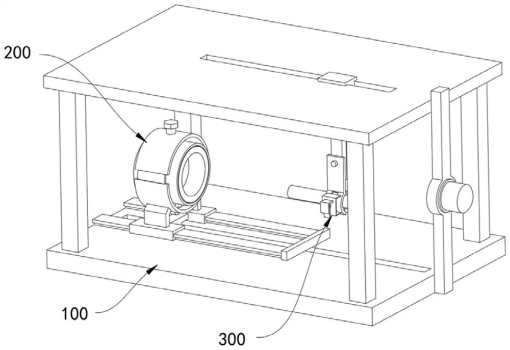
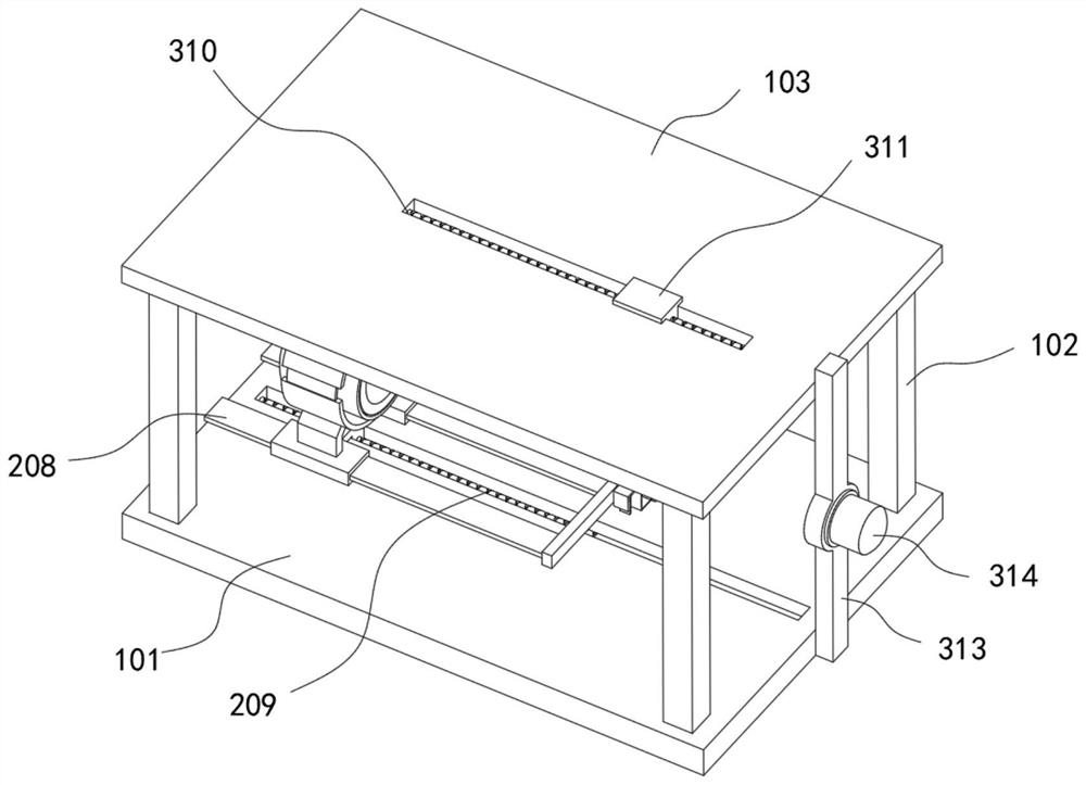
[0030] refer to Figure 1-5 , a motor testing tool, comprising: a support structure 100, including a support base plate 101 and a plurality of support columns 102 evenly connected to the upper end of the support base plate 101, the upper ends of the plurality of support columns 102 are fixedly connected with a same horizontal support top plate 103 .

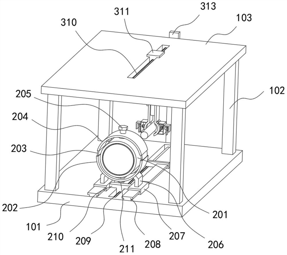
[0031] The casing structure 200 includes a motor casing 201 , and a limit unit connected to the outer side of the motor casing 201 is provided. The upper end of the bottom plate 202 is slidably connected with two movable plates 203, and the upper ends of the two movable plates 203 are fixedly connected with the same arc-shaped top plate 204, and the upper end of the arc-shaped top plate 204 is threadedly connected with a vertical fastening screw 205, and The lower end of the tightening screw 205 is fixedly connected with a limit block which is in contact with the motor housing 201 .

[0032] Further, the upper end of the suppor...


PUM


Abstract

The invention belongs to the technical field of motor test tools, and particularly relates to a motor test tool, which comprises a support structure comprising a support bottom plate and a plurality of support columns uniformly distributed and connected to the upper end of the support bottom plate, and the upper ends of the plurality of support columns are fixedly connected with a same horizontal support top plate; the machine shell structure comprises a motor shell, a limiting unit connected with the motor shell is arranged on the outer side of the motor shell, and a conveying unit connected with the limiting unit is arranged at the upper end of the supporting bottom plate; and the rotating shaft structure comprises a rotating shaft, the rotating shaft and the axis of the motor shell are collinear and are oppositely arranged, a clamping unit is arranged on the outer side of the rotating shaft, and a hoisting unit connected with the clamping unit is arranged at the upper end of the supporting top plate. The device is suitable for assembling motor shells and rotating shafts of different sizes, the clamping structure can be removed after the rotating shaft is assembled, balance testing is carried out, and stable use of a rotor is guaranteed.

Description

technical field [0001] The invention relates to the technical field of motor testing tooling, in particular to a motor testing tooling and a method for using the same. Background technique [0002] Various revolving bodies in engineering, due to various factors such as uneven material or blank defects, errors in processing and assembly, and even asymmetric geometric shapes in design, so that when the revolving body rotates, each on its The centrifugal inertial force generated by the tiny particles cannot cancel each other out. The centrifugal inertial force acts on the machine and its foundation through the bearing, causing vibration, producing noise, accelerating bearing wear, shortening the life of the machine, and causing destructive accidents in severe cases. [0003] When assembling traditional motors, special fixtures are usually used to fix the motor casing, and then the motor rotor is assembled. Although the fixtures can ensure the stability of the motor casing to a ...

Claims


Application Information

Patent Timeline
IPC IPC(8): G01M1/14G01M1/06
CPCG01M1/14G01M1/06
Inventor 徐榕锋
Owner NANJING GAOQI ELECTRIC
Why Eureka
Try Eureka