Eureka AIR delivers breakthrough ideas for toughest innovation challenges, trusted by R&D personnel around the world.

Press type self-ligating bracket

A self-locking bracket, pressing technology, applied in brackets, arch wires, etc., can solve the problems of cumbersome operation, long-lasting clinical process, increase the operation time of orthodontists, etc., and achieve the effect of reliable opening and closing.

Pending Publication Date: 2022-04-12
GRINM MEDICAL INSTR BEIJING CO LTD
View PDF0 Cites 0 Cited by
  • Summary
  • Abstract
  • Description
  • Claims
  • Application Information

AI Technical Summary

Problems solved by technology

[0003] The self-ligating bracket in the related art includes a bracket main body, a base plate fixed on the bracket main body, and an arch wire slot provided on the side of the bracket main body away from the base plate, and the arch wire slot is used for embedding the main arch wire Among them, the bracket body and the main arch wire are fixed; in order to ensure the installation stability between the main arch wire and the bracket body, the bracket body is provided with a sliding locking plate for closing or opening the arch wire slot; when the arch wire needs to be opened and closed When using the wire groove, the orthodontist needs to use the supporting unlocking tool to open and close the lock. The operation is cumbersome and the clinical process by the chair is long-lasting, which increases the operation time of the orthodontist and affects the orthodontic effect

Method used


Image

  • Press type self-ligating bracket
  • Press type self-ligating bracket
  • Press type self-ligating bracket

Examples


Embodiment Construction

[0038] In the description of the present application, it should be noted that the terms "approaching", "far away from", "deviating from", and "facing" are all based on the relative relationship shown in the drawings, and are only for the convenience of describing the present invention and simplifying the description. It does not indicate or imply that the process or module referred to must have a specific orientation, state and operation, and thus should not be construed as limiting the invention.

[0039] The application will be described in further detail below in conjunction with the accompanying drawings.

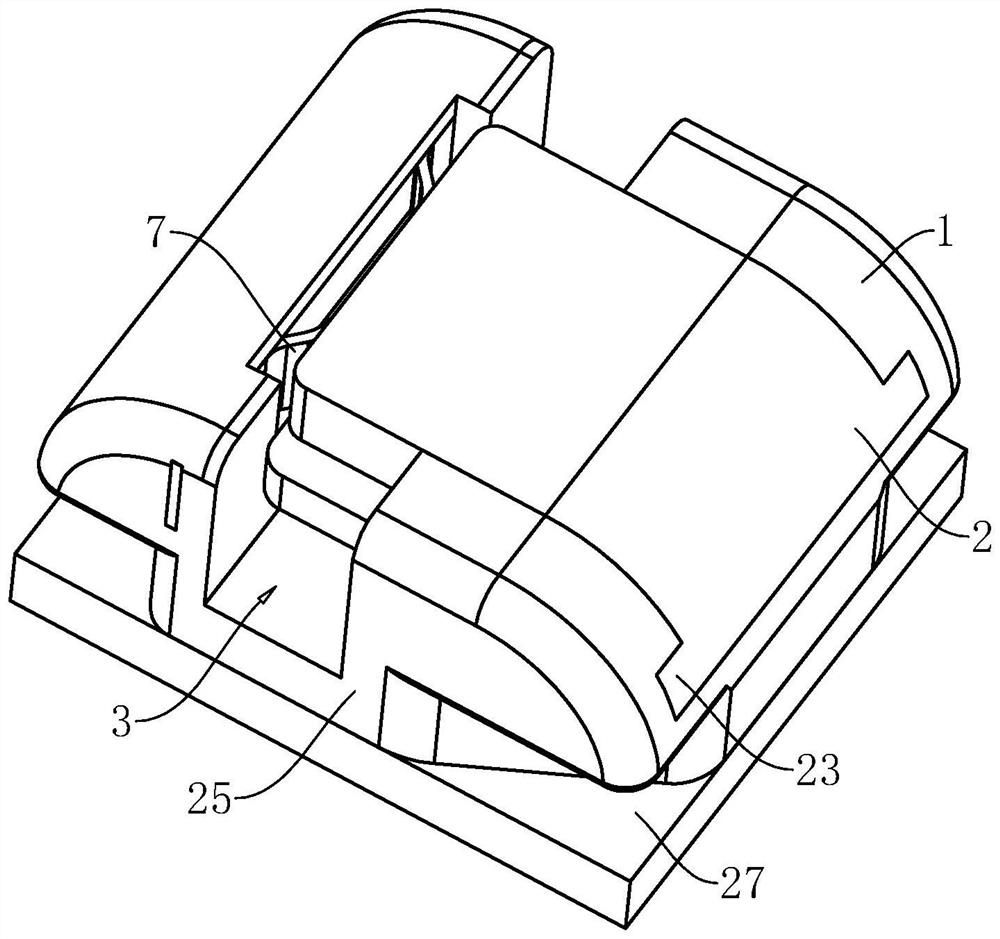
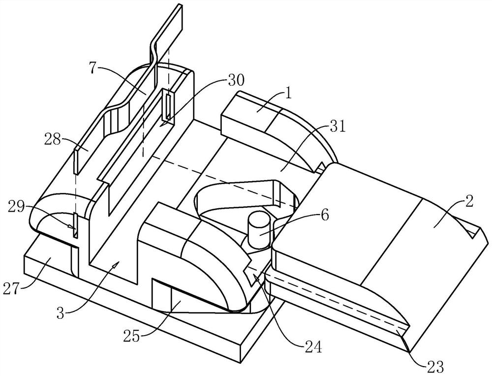
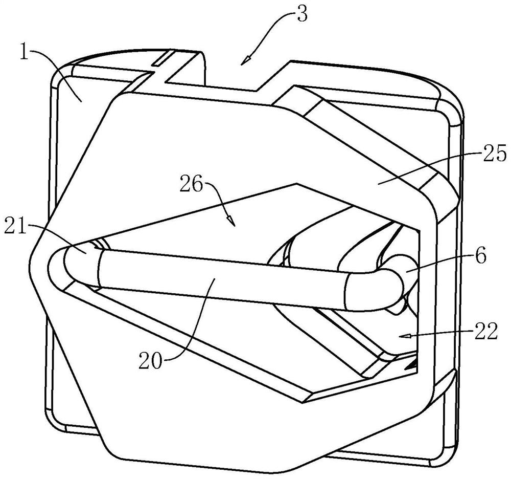
[0040] refer to figure 1 with figure 2 , the application provides a push-type self-locking bracket, including a bracket body 1, an archwire slot 3 set on the bracket body 1, a sliding sliding bracket located on the bracket body 1 and set on one side of the archwire slot 3 surface 31, the sliding locking piece 2 that can slide on the sliding surface 31 toward or away ...


PUM


Abstract

The invention relates to an orthodontic medical instrument, in particular to a push type self-ligating bracket which is characterized by comprising a bracket body and a sliding locking plate, and an arch wire groove is formed in the bracket body; the sliding locking plate is provided with a closing locking groove and an opening and closing locking groove with openings facing away from the arch wire groove; the bracket main body is provided with a locking block capable of performing position switching between the opening and closing locking groove and the closing locking groove; the bracket main body is provided with a force applying piece for applying an acting force to the locking block so that the locking block can be maintained in the opening and closing locking groove or the closing locking groove; the sliding lock plate is provided with a closed transition groove, an opening and closing transition groove, a first opening and closing channel communicating the opening and closing transition groove with the closed lock groove, a second opening and closing channel communicating the opening and closing transition groove with the opening and closing lock groove, a first closed channel communicating the opening and closing lock groove with the closed transition groove, and a second closed channel communicating the closed transition groove with the closed lock groove. The purpose of facilitating opening and closing of the arch wire groove so as to save the operation time of an orthodontic doctor is achieved.

Description

technical field [0001] The present application relates to an orthodontic medical device, in particular to a push-type self-locking bracket. Background technique [0002] The self-locking bracket is the main part of the fixed appliance. During the clinical correction cycle, it is necessary to open the lock of the bracket many times, readjust the arch wire, polish, bend or directly replace it. [0003] The self-ligating bracket in the related art includes a bracket main body, a base plate fixed on the bracket main body, and an arch wire slot provided on the side of the bracket main body away from the base plate, and the arch wire slot is used for embedding the main arch wire Among them, the bracket body and the main arch wire are fixed; in order to ensure the installation stability between the main arch wire and the bracket body, the bracket body is provided with a sliding locking plate for closing or opening the arch wire slot; when the arch wire needs to be opened and closed...

Claims


Application Information

Patent Timeline
IPC IPC(8): A61C7/34A61C7/28
Inventor 董显峰廖赞姜英奇张宝祥王振强于学保崔煦李君涛
Owner GRINM MEDICAL INSTR BEIJING CO LTD
Why Eureka
Eureka Blog
Learn More