Combined mold for injection molding of parts and use method of combined mold
A component and combined technology, which is applied in the field of combined molds for injection molding of components, can solve problems such as failure to take out normally, parts sticking, deformation, etc., and achieve the effect of solving the inconvenience of taking out injection molded products and taking them quickly
- Summary
- Abstract
- Description
- Claims
- Application Information
AI Technical Summary
Problems solved by technology
Method used
Image

Examples
Embodiment 1
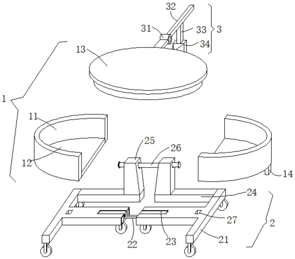
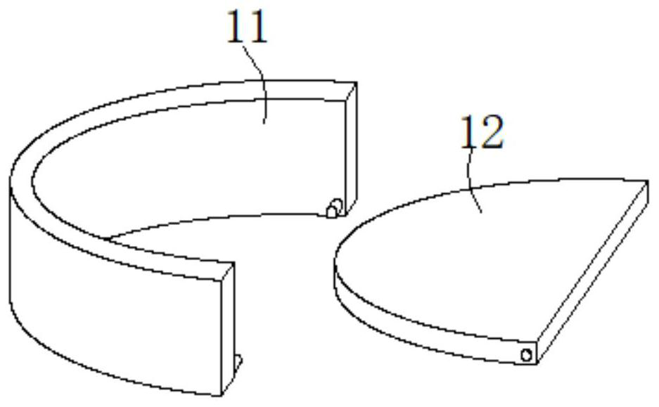
[0030] see Figure 1-5 , the present embodiment provides a combined mold for injection molding parts and its use method, including a mold 1 and a support mechanism 2, the mold 1 includes an upper mold 13 and two lower molds 11 that can be assembled together, and the lower mold 11 is Semi-circular pallet, the inner bottom of the semi-circular pallet is rotated by a pin shaft to provide a semi-circular bottom plate 12, and the two semi-circular pallets are assembled into a hollow cylindrical mold cavity after facing each other, and the upper mold is covered by 13 Fit in the mouth position of the hollow cylindrical mold cavity, butt the two semicircular clamps together, and then cover the upper mold 13 to form an assembled mold to perform injection molding on the parts.
[0031] The upper mold 13 and the lower mold 11 can be rectangular or polygonal, and the shapes of the upper mold 13 and the lower mold 11 can be set arbitrarily according to injection molding requirements, so as...
Embodiment 2
[0038] see Figure 1-5 , further improvements have been made on the basis of Example 1:
[0039] The corner position of the bottom end of the T-shaped base 21 is provided with brake universal wheels, and by setting the brake universal wheels, the sliding friction force when the T-shaped base 21 slides is reduced.
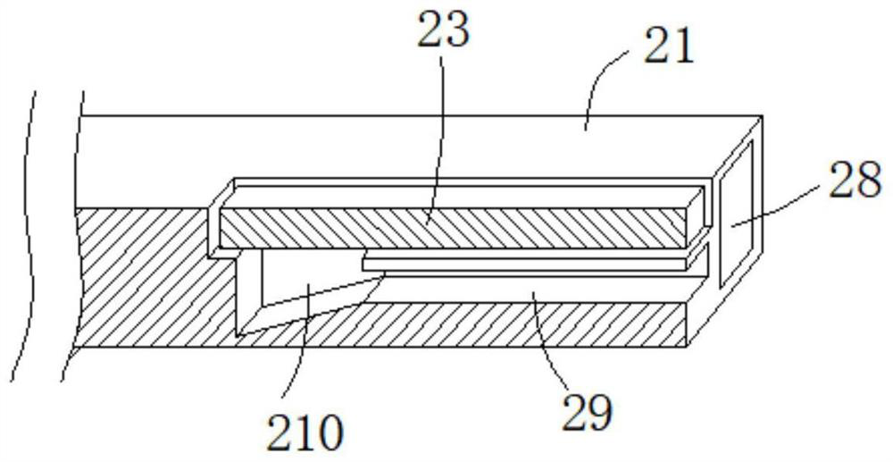
[0040] In order to compensate the height difference when the top block 212 slides along the inside of the jacking groove 210, a T-shaped slot 213 is opened on the side wall of the top block 212, and the end of the beam 22 is fixed with a T-shaped block that slides and engages with the T-shaped slot 213 211 , while the jacking block 212 slides horizontally with the beam 22 , it can slide through the T-shaped slot 213 and the T-shaped block 211 , so as to compensate the height difference when the jacking block 212 slides along the inside of the jacking slot 210 .
[0041] The opposite side walls of the two T-shaped bases 21 are fixedly embedded with electromagnets 28...
PUM
 Abstract
Description
Claims
Application Information