Self-steering composite wheel

A composite wheel, self-steering technology, applied in the directions of wheels, transportation and packaging, vehicle components, etc., can solve the problems of space occupation and complex steering structure, and achieve the effect of compatibility between steering flexibility and space compactness

Pending Publication Date: 2022-04-12
陈雪旌
View PDF0 Cites 0 Cited by
  • Summary
  • Abstract
  • Description
  • Claims
  • Application Information

AI Technical Summary

Problems solved by technology

Ordinary steering wheels require a separate steering mechanism and a stabilization mechanism for driving the wheels, and at the same time, it is necessary to reserve space for the wheels within the steering limit, which makes the space occupation and steering structure more complicated.
[0004] Based on the above-mentioned existing technologies, when the application scene requires steering, small space occupation and stable structural design at the same time, it is difficult to achieve it with the existing technologies. Therefore, it is necessary to design a self-steering wheel that does not change the structure autonomous steering

Method used


Image

  • Self-steering composite wheel
  • Self-steering composite wheel
  • Self-steering composite wheel

Examples


Embodiment 1

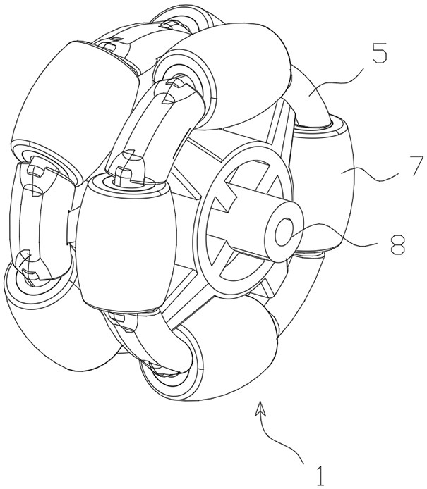
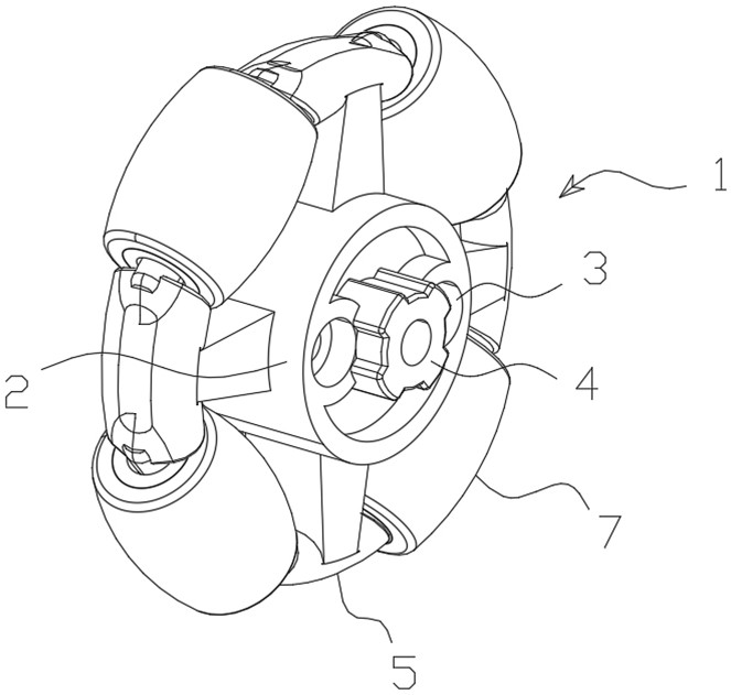
[0039] Combined with the manual Figure 1-Figure 3 The shown self-steering composite wheel includes at least one composite mechanism 1 that forms the self-steering composite wheel, and the composite mechanism 1 includes a support mechanism 2 as the structural skeleton of the self-steering composite wheel and a plurality of runners 7 for steering; At least one end surface of the support mechanism 2 is provided with a travel shaft 8, and a plurality of runners 7 are evenly distributed on the outer peripheral side of the support mechanism 2 with the axis center of the travel shaft 8 as the center of a circle and are located on the same or parallel to each other. In the radial plane of the radial axis 8 , any running wheel 7 is rotatably connected with the supporting mechanism 2 .

[0040] Explanation of structure and principle:

[0041] The compound mechanism 1 is the structural unit that forms the self-steering compound wheel. A self-steering compound wheel can choose one compo...

Embodiment 2

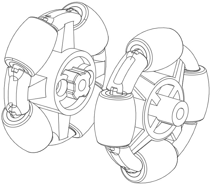
[0045] In order to better adapt to most currently known application scenarios, on the basis of Embodiment 1, this embodiment further combines the Figure 1-Figure 9 The self-steering compound wheel shown is further optimized in structure, as follows:

[0046] In order to better realize the rotation of the runner 7 while satisfying the normal non-steering rotation, preferably, a plurality of arms 5 are distributed on the support mechanism 2 with the axis of travel 8 as the center line, and the two arms of any arm 5 Each end is provided with a steering shaft 6 for mounting the running wheel 7, and the running wheel 7 is rotationally connected with the steering shafts 6 on two adjacent support arms 5.

[0047] In order to improve the stressed state of the runner 7 and at the same time ensure that the runner 7 is in a good rotational connection state, preferably, a sleeve 9 is arranged inside the runner 7, and the two ends of the sleeve 9 are connected to the adjacent image respec...


PUM


Abstract

The invention discloses a self-steering composite wheel which comprises at least one composite mechanism forming the self-steering composite wheel, and each composite mechanism comprises a supporting mechanism serving as a self-steering composite wheel structural framework and a plurality of rotating wheels used for steering. At least one end face of the supporting mechanism is provided with a travel path shaft, the multiple rotating wheels are evenly distributed on the peripheral side of the supporting mechanism with the axis of the travel path shaft as the circle center and located in the same or multiple parallel radial planes penetrating through the travel path shaft, and any rotating wheel is rotationally connected with the supporting mechanism. According to the self-steering composite wheel, the multiple rotating wheels are arranged on the supporting mechanism of the composite wheel, when the combined external force is perpendicular to the travel path shaft of the composite wheel, the rotating wheels rotate relative to the travel path shaft and only revolve, and the steering effect is not generated; and when the combined external force is not perpendicular to the travel path shaft of the composite wheel, the rotating wheel generates self-adaptive autorotation during revolution, so that the effect of simultaneously steering in the travel path process is realized.

Description

technical field [0001] The invention relates to the technical field of steering wheels, in particular to a steering wheel that realizes steering without angular deflection of a traveling shaft, and in particular to a self-steering compound wheel. Background technique [0002] The steering wheel is an indispensable structural component when the structural device uses the roller to move and steer. The steering structure of the existing structural device can be roughly divided into two types according to the steering principle: one is the steering wheel steering, and the common ones are motorcycles. , cars and other tools that use wheels to move; the other is differential steering, and the common representative structure is a crawler track structure device, such as tanks, excavators and other construction machinery. [0003] Differential steering is generally not suitable for most mobile devices. Because it needs to overcome the huge friction on the steering side, it needs to c...

Claims


Application Information

Patent Timeline
Patent Type & Authority Applications(China)
IPC IPC(8): B60B19/00
Inventor 陈雪旌
Owner 陈雪旌
Why Eureka
Try Eureka