
Electromagnetic floating type lifting appliance

A floating type and spreader technology, applied in the field of spreaders, can solve the problems of steel plate electromagnet damage, damage, head-to-head, etc., and achieve the effect of preventing head-to-head

Pending Publication Date: 2022-04-12
常州飞石机器人系统有限公司
View PDF0 Cites 0 Cited by
  • Summary
  • Abstract
  • Description
  • Claims
  • Application Information

AI Technical Summary

Problems solved by technology

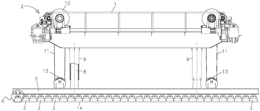
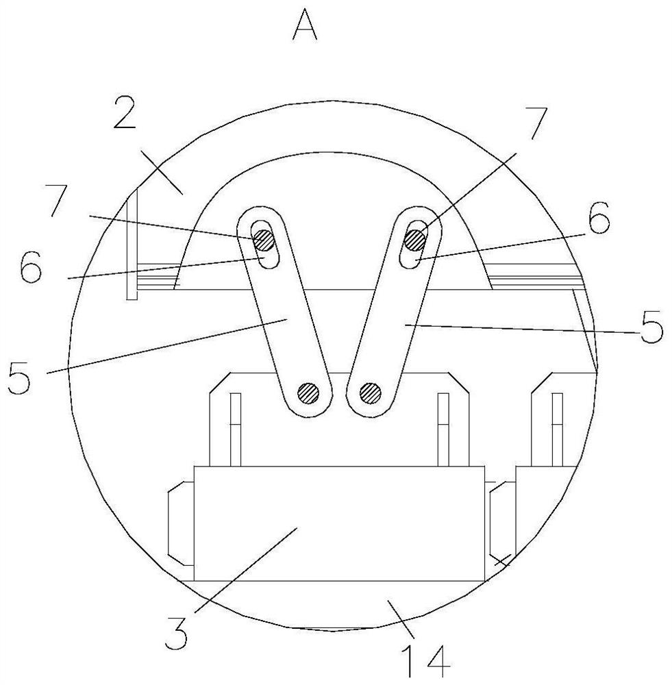
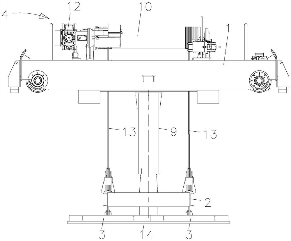
[0004] The technical problem to be solved by the present invention is: in order to solve the problem that when the electromagnet of the existing magnetic suction type sling absorbs the steel plate, head-to-head collision between the electromagnet and the steel plate is easy to occur, which will cause damage to the steel plate or the electromagnet, affecting the The quality of the equipment or the steel plate, thus causing unnecessary damage, now provides an electromagnetic floating spreader

Method used


Image

  • Electromagnetic floating type lifting appliance
  • Electromagnetic floating type lifting appliance
  • Electromagnetic floating type lifting appliance

Examples


Embodiment Construction

[0019] The present invention is described in further detail below in conjunction with embodiment:

[0020] The present invention is not limited to the following specific embodiments. Those skilled in the art can implement the present invention in various other specific embodiments according to the disclosed content of the present invention, or make simple changes or Modifications all fall within the protection scope of the present invention. It should be noted that, in the case of no conflict, the embodiments of the present invention and the features in the embodiments can be combined with each other.

[0021] In describing the present invention, it should be understood that the terms "center", "longitudinal", "transverse", "upper", "lower", "front", "rear", "left", "right", " The orientations or positional relationships indicated by "vertical", "horizontal", "top", "bottom", "inner" and "outer" are based on the orientations or positional relationships shown in the drawings, ...


PUM


Abstract

The invention relates to the technical field of lifting appliances, in particular to an electromagnetic floating type lifting appliance which comprises a plurality of trusses, a fixing frame and a plurality of electromagnets arranged in an array mode, a lifting mechanism used for driving the fixing frame to ascend or descend is arranged on the trusses, and the electromagnets are arranged on the fixing frame in a floating mode. When the electromagnetic floating type lifting appliance is used, the electromagnets which are arranged in an array mode are arranged on the fixing frame in a floating mode, so that the electromagnets have a certain moving space, the electromagnets are prevented from colliding with a steel plate in a hard mode, the electromagnets have a certain buffering space, and therefore the electromagnets are prevented from being damaged. The problems that when an electromagnet of an existing magnetic type lifting appliance attracts a steel plate, the phenomenon that the electromagnet and the steel plate collide with each other easily occurs, so that the steel plate or the electromagnet is damaged, the quality of equipment or the steel plate is affected, and unnecessary damage is caused are solved.

Description

technical field [0001] The invention relates to the technical field of slings, in particular to an electromagnetic floating sling. Background technique [0002] The permanent magnetic crane is designed using the principle of continuity of magnetic flux and the principle of superposition of magnetic fields. The magnetic circuit of the permanent magnetic crane is designed into multiple magnetic systems. Through the relative movement of the magnetic systems, the phase of the magnetic field intensity on the working magnetic pole surface is realized Add or cancel, so as to achieve the purpose of work or unloading. [0003] Since the ordinary spreader only hangs the four corners of the steel plate when lifting the steel plate, the lifting of the steel plate is unstable and prone to rollover of the steel plate. When the electromagnet of the tool absorbs the steel plate, it is easy to have a head-to-head phenomenon between the electromagnet and the steel plate, which will cause dam...

Claims


Application Information

Patent Timeline
Patent Type & Authority Applications(China)
IPC IPC(8): B66C1/06B66C13/06B66D1/00B66D1/14
Inventor 刘金石李国亮余鹏
Owner 常州飞石机器人系统有限公司
Learn More