Drain valve based on safety improvement

A steam trap and safety technology, applied in steam traps, flange connections, passing components, etc., can solve the problems of low safety of steam traps, small fault tolerance space, pipeline deformation, etc., and achieve high disassembly and maintenance efficiency, High safety and stability

Active Publication Date: 2021-09-17
HUANENG QINMEI RUIJIN POWER GENERATION CO LTD
View PDF22 Cites 0 Cited by
  • Summary
  • Abstract
  • Description
  • Claims
  • Application Information

AI Technical Summary

Problems solved by technology

[0002] The function of the steam trap (referred to as the trap) is to automatically remove non-condensable gases such as steam condensed water and air in the heating equipment or steam pipeline, and not to leak steam. Because the trap has the function of blocking steam and draining water, it can make the steam heating equipment Uniform heat supply, make full use of steam latent heat to prevent water hammer in the steam pipeline, there are many types of steam traps, each with different performance, when selecting a steam trap, firstly choose its characteristics to meet the best operation of the steam heating equipment, and then Considering other objective conditions, it is correct and effective to choose the steam trap you need. The steam traps in the prior art are generally installed in the air or fixed on the wall by screws. During the use of the pipe, it is easy to cause the pipe to be subjected to excessive force and cause large deformation, resulting in breakage, etc., but the way of installing the trap on the wall has less room for error, and the trap needs a certain buffer space during use. In order to avoid the breakage of the connection between the trap and the pipeline, this method will lead to low safety during the use of the trap, and there will be a lot of inconvenience

Method used


Image

  • Drain valve based on safety improvement
  • Drain valve based on safety improvement
  • Drain valve based on safety improvement

Examples


Embodiment 1

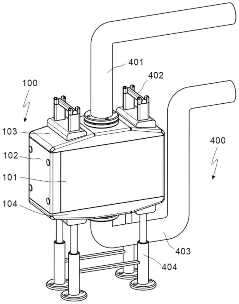
[0032] refer to figure 1 , 6 , 8 and 9 are the first embodiment of the present invention, which provides a safety-improving steam trap. The safety-improving steam trap includes a valve body assembly 100 , a control assembly 200 , an installation assembly 300 and The connection assembly 400, through the arrangement of the connection assembly 400, makes the steam trap more stable during use.

[0033] Specifically, the valve body assembly 100 includes a casing 101 , a fastener 102 disposed on one side of the casing 101 , a water inlet 103 disposed on the top of the casing 101 , and a water outlet 104 disposed at the bottom of the casing 101 . The valve body is provided with a water inlet 103 to improve the efficiency of water and steam inlet, thereby improving the efficiency of the valve in the working process.

[0034]The control assembly 200 is arranged inside the housing 101, and includes a valve seat 201 arranged on the inner bottom wall of the housing 101, a valve flap 202...

Embodiment 2

[0039] refer to Figures 2 to 5 , is the second embodiment of the present invention, which is based on the previous embodiment.

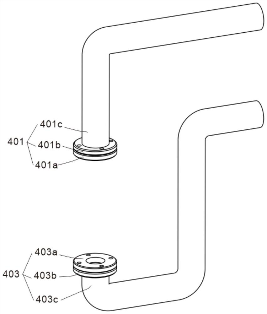
[0040] Specifically, the first connecting member 401 includes a first flange 401a disposed on the top of the water inlet member 103, a second flange 401b disposed on the top of the first flange 401a, and a first flange 401b disposed on the top of the second flange 401b In the pipeline 401c, the first flange 401a and the second flange 401b are screwed together, and the first pipeline 401c is connected with the water inlet pipe in the pipeline through the connection between the first flange 401a and the second flange 401b. The cooperation makes the connection between the first pipe 401c and the water inlet pipe 103b more convenient and stable.

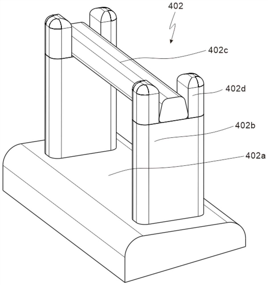
[0041] Preferably, the guard 402 includes a first plate 402a disposed on the top of the housing 101, a fixing block 402b disposed on the top of the first plate 402a, a handle 402c disposed on the top of the f...

Embodiment 3

[0046] refer to Figures 6 to 10 , is the third embodiment of the present invention, which is based on the first two embodiments.

[0047] Specifically, the water inlet 103 includes a first fixing plate 103a arranged on the top of the casing 101, a water inlet pipe 103b arranged in the middle of the first fixing plate 103a, a fixing frame 103c arranged on the inner top wall of the casing 101, The guide plates 103d on both sides of the frame 103c, and the filters 103e arranged on both sides of the fixing frame 103c, the water inlet pipe 103b is arranged above the fixing frame 103c, and the water outlet 104 includes a second fixing plate 104a arranged at the bottom of the casing 101 , a water outlet pipe 104b arranged in the middle of the second fixed plate 104a, and a first emptying groove 104c arranged inside the second fixed plate 104a and communicated with the water outlet pipe 104b, when the condensed water enters the inside of the valve through the water inlet pipe 103b A...


PUM


Abstract

The invention discloses a drain valve based on safety improvement. The drain valve based on safety improvement comprises a valve body assembly, a control assembly and mounting assemblies, the valve body assembly comprises a shell, a fastener arranged on one side of the shell, a water inlet piece arranged on the top of the shell, and a water outlet piece arranged at the bottom of the shell. The control assembly is arranged in the shell and comprises a valve seat arranged on the inner bottom wall of the shell, a valve clack arranged on the top of the valve seat, a flow guide part arranged in the valve seat and a floating ball part arranged on the top of the valve clack. The mounting assemblies are arranged on the inner bottom wall of the shell and located on the two sides of the valve seat. According to the drain valve based on safety improvement, through the arrangement of the control assembly and the mounting assemblies, the disassembly, assembly and maintenance efficiency of the drain valve is higher, meanwhile, the drain valve is more convenient to use, then through the arrangement of a connecting assembly, the stability of the drain valve is higher when the drain valve is connected to a pipeline, a certain buffer space is provided, the probability of breakage of the joint between the drain valve and the pipeline is greatly reduced, and the safety is higher.

Description

technical field [0001] The invention relates to the technical field of steam traps, in particular to a steam trap based on improved safety. Background technique [0002] The function of the steam trap (referred to as the trap) is to automatically remove non-condensable gases such as steam condensed water and air in the heating equipment or steam pipeline, and no steam leaks. Evenly supply heat, make full use of the latent heat of steam to prevent water hammer in the steam pipeline. There are many types of traps, each with different performance. When selecting a trap, first of all, its characteristics should be selected to meet the optimal operation of the steam heating equipment, and then Considering other objective conditions, it is correct and effective to choose the trap you need. The traps in the prior art are generally installed in the air or fixed on the wall by screws. During the use process, it is easy to cause the pipeline to be overstressed and cause large deforma...

Claims


Application Information

Patent Timeline
Patent Type & Authority Applications(China)
IPC IPC(8): F16T1/20F16T1/38F16T1/45F16L23/02F16F15/08
CPCF16T1/20F16T1/383F16T1/386F16T1/45F16L23/02F16F15/08
Inventor 杨行炳徐良周建松吕海涛石伟栋张建忠郭通李强张捷文作伟朱致军刘晓航王东升
Owner HUANENG QINMEI RUIJIN POWER GENERATION CO LTD
Why Eureka
Try Eureka