An intelligent combined electrical isolation and grounding interconnection device on a pole
An intelligent and electrical technology, applied in the direction of electrical components, circuits, electrical switches, etc., can solve the problems of inconvenient operation for maintenance personnel, and achieve the effects of saving costs, convenient operation, and ensuring personal safety
- Summary
- Abstract
- Description
- Claims
- Application Information
AI Technical Summary
Problems solved by technology
Method used
Image
Examples
Embodiment 1
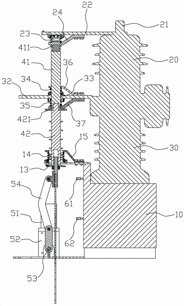
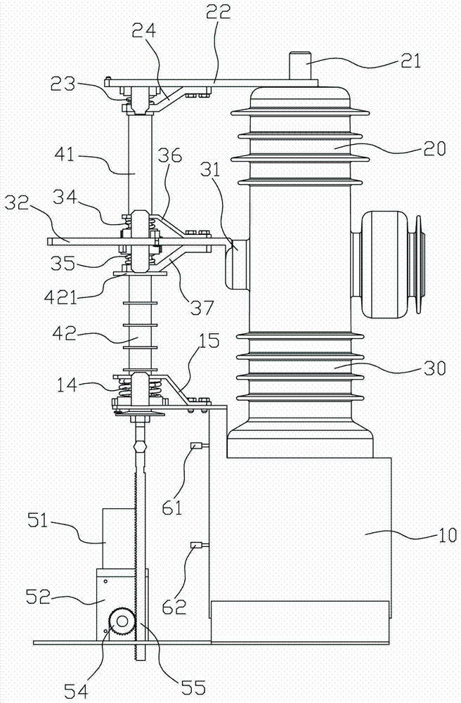
[0029] An intelligent combination electric on the pole, refer to figure 1 and figure 2 , including a box body 10, the box body 10 is provided with three upper insulating cylinders 20 and three lower insulating cylinders 30, the top of the upper insulating cylinder 20 is provided with an incoming line joint 21, and the side wall of the lower insulating cylinder 30 is provided with an outgoing line joint 31 . The intelligent combination electric on the column also includes a power-off and grounding interconnection device, and the power-off and grounding interconnection device includes an incoming line guide plate 22 and an outgoing line guide plate 32 respectively connected to the incoming line connector 21, the outgoing line joint 31, and the side of the box body 10. As well as the ground guide plate 12, the incoming line guide plate 22, the outgoing line guide plate 32 and the ground guide plate 12 are in the same vertical plane.
[0030] refer to Figure 2 to Figure 4 A f...
Embodiment 2
[0035] refer to Figure 5 and Image 6 , the present embodiment is basically the same as the first embodiment, the difference lies in the structure of the power mechanism, the power mechanism of the present embodiment includes a motor 51, a reduction box 52, a transmission shaft 53 and a plurality of gears 54 and racks 55 , the motor 51 is connected to the transmission shaft 53 through the reduction box 52, the transmission shaft 53 is horizontally arranged on the side of the casing 10, and a plurality of gears are arranged on the transmission shaft 53 at intervals, and each gear 54 The side faces are respectively engaged with a toothed rack 55 , and the upper end of each toothed rack 55 is respectively connected to the lower end of the insulating rod 42 . When the motor 51 is working, its output shaft makes the transmission shaft 53 rotate in the horizontal plane under the action of the reduction box 52, so that the gear 54 rotates up and down, and the rack rises and falls u...
Embodiment 3
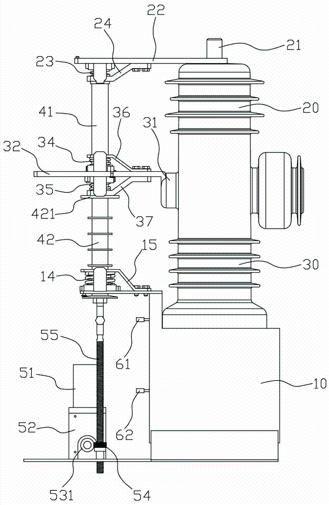
[0037] refer to Figure 7 and Figure 8 , the present embodiment is basically the same as the first embodiment, the difference lies in the structure of the power mechanism, the power mechanism of the present embodiment includes a motor 51, a reduction box 52, a worm shaft 53 and a plurality of worm gears 54 and screw rods 55, the motor 51 is connected to the worm shaft 53 through the reduction box 52, the worm shaft 53 is horizontally arranged on the side of the box body 10, the worm shaft 53 is provided with a plurality of thread segments 531 at intervals, each thread segment 531 The sides of each worm wheel 54 are correspondingly meshed with a worm wheel 54, and the center of each worm wheel 54 is provided with an internally threaded hole, and one of the screw rods 55 is respectively connected in the internally threaded hole, and the upper end of each screw rod 55 is correspondingly connected to the insulating The lower end of the rod 42. When motor 51 was working, its out...
PUM
 Abstract
Description
Claims
Application Information
 - R&D
- Intellectual Property
- Life Sciences
- Materials
- Tech Scout
- Unparalleled Data Quality
- Higher Quality Content
- 60% Fewer Hallucinations
Browse by: Latest US Patents, China's latest patents, Technical Efficacy Thesaurus, Application Domain, Technology Topic, Popular Technical Reports.
© 2025 PatSnap. All rights reserved.Legal|Privacy policy|Modern Slavery Act Transparency Statement|Sitemap|About US| Contact US: help@patsnap.com


