Supercharge Your Innovation With Domain-Expert AI Agents!

Ampoule bottle scratching equipment

An ampoule bottle and scratching technology, which is applied in the field of ampoule bottle scratching equipment, can solve the problems of unsteady ampoule bottle, low efficiency, labor consumption, etc., and achieve the effect of automatically clamping and stabilizing the ampoule bottle.

Pending Publication Date: 2022-04-12
刘连会
View PDF6 Cites 0 Cited by
  • Summary
  • Abstract
  • Description
  • Claims
  • Application Information

AI Technical Summary

Problems solved by technology

[0003] The existing ampoule bottle scratching technology generally requires the user to manually use a cutter to cut the mark on the ampoule bottle mouth to facilitate the use of the ampoule bottle. Only one ampoule can be scratched at a time, which is inefficient. Secondly, it is dangerous to operate with two hand-held cutters. Finally, when scratching the ampoule, the ampoule is not firmly held, and it may fall over and affect the scratch.

Method used


Image

  • Ampoule bottle scratching equipment
  • Ampoule bottle scratching equipment
  • Ampoule bottle scratching equipment

Examples


Embodiment 1

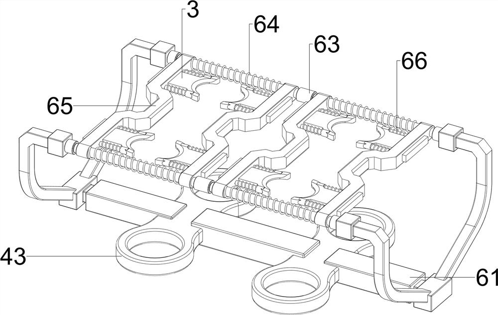
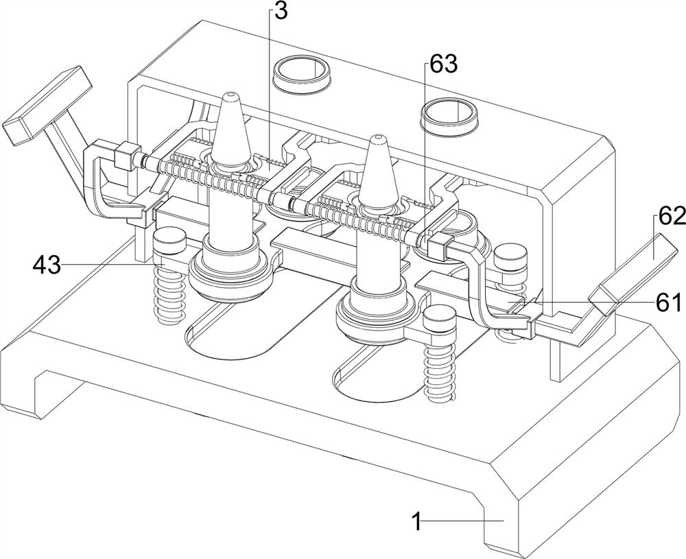
[0029] Such as Figure 1 to Figure 6 As shown, this embodiment discloses an ampoule bottle scratching device, including a base 1, an outer cover 2, a cutter 3, a placing mechanism 4, a rotating mechanism 5 and a translation mechanism 6, the upper part of the base 1 is connected with the outer cover 2, and the upper part of the base 1 A placement mechanism 4 is provided, a rotation mechanism 5 is provided on the base 1, a translation mechanism 6 is provided on the upper side of the outer cover 2, and two cutting knives 3 are arranged symmetrically on both sides of the front and back of the translation mechanism 6.

[0030] The placement mechanism 4 includes a first guide rod 41, a first spring 42, a placement frame 43 and a rotating disk 44. The front and rear sides of the top of the base 1 are symmetrically connected with the first guide rod 41, and the first guide rods 41 are connected in a sliding manner. There is a placement frame 43, and the front and rear sides between th...

Embodiment 2

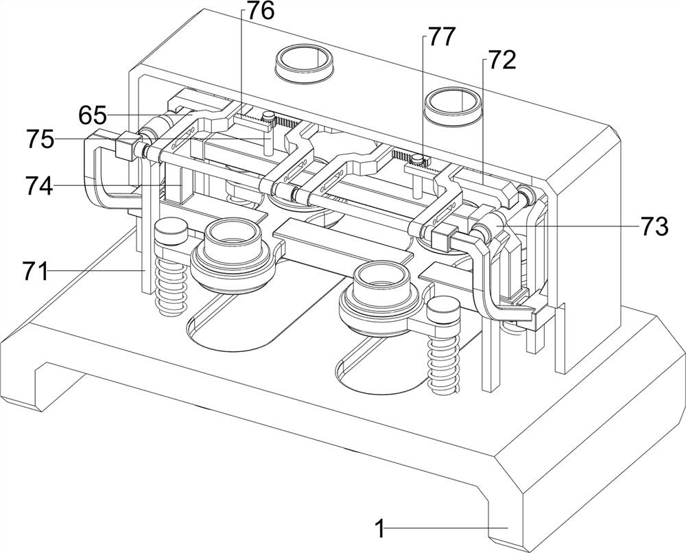
[0035] Such as figure 2 , Figure 7 ~ Figure 10 As shown, in some embodiments, a closing mechanism 7 is also included, and the closing mechanism 7 includes a limit rod 71, a second mounting frame 72, a contact wheel 73, a third mounting frame 74, a fixed shaft 75, and a first rack 76 With the first gear 77, the left and right sides of the base 1 top are all symmetrically connected with the limit rod 71, the outside of the middle part of the housing slide bar 65 is connected with the second mounting bracket 72, and the front and rear symmetrical rotation of the bottom of the second mounting bracket 72 is connected with a coupler. The contact wheel 73, the contact wheel 73 cooperates with the limit lever 71, the third mounting frame 74 is connected between the first mounting frame 61 top, the left and right sides of the third mounting frame 74 top are connected with the fixed shaft 75, the fixed shaft 75 The upper part is rotatably connected with a first gear 77 , and the inne...


PUM


Abstract

The invention discloses an ampoule bottle scratching device. The technical problem of the invention is to provide the ampoule bottle scratching equipment which is convenient to move, drives ampoule bottles to rotate and easily realizes batch scratching of the ampoule bottles. An ampoule bottle scratching device comprises a base, and an outer cover is connected to the upper portion of the base. The placing mechanism is arranged at the upper part of the base; the rotating mechanism is arranged on the base; the translation mechanism is arranged on the upper side in the outer cover; and the two cutters are symmetrically arranged on the two sides of the translation mechanism. The ampoule bottle scratching equipment disclosed by the invention has the advantages that the ampoule bottle can be conveniently driven to rotate to finish scratching, the cutter is automatically moved to scratch the ampoule bottle, and the ampoule bottle is automatically clamped and stabilized.

Description

technical field [0001] The invention relates to a scratching device, in particular to an ampoule bottle scratching device. Background technique [0002] Ampoule bottle is a small glass container used to hold medicinal liquid. The capacity is generally 1-25ml. It is often used to store drugs for injection, vaccines, serum, etc. It is also used for packaging of oral liquid. The related medicines in ampoule bottle packaging need to be used When using, it is necessary to scratch the ampoule bottle to facilitate the opening of the ampoule bottle. [0003] The existing ampoule bottle scratching technology generally requires the user to manually use a cutter to cut the mark on the ampoule bottle mouth to facilitate the use of the ampoule bottle. Only one ampoule can be scratched at a time, which is inefficient. Secondly, it is dangerous to operate with two hand-held cutters. Finally, when scratching the ampoule, the ampoule is not firmly held, and it may fall over and affect the s...

Claims


Application Information

Patent Timeline
IPC IPC(8): B67B7/60
Inventor 刘连会
Owner 刘连会
Features
  • R&D
  • Intellectual Property
  • Life Sciences
  • Materials
  • Tech Scout
  • Unparalleled Data Quality
  • Higher Quality Content
  • 60% Fewer Hallucinations
Learn More