Automatic grass grid laying machine

An automatic grass and laying machine technology, applied in the field of greening, can solve the problems of unsuitable large-area laying grass squares, a large number of manpower and tools, low efficiency, etc., and achieve the effect of laying hay efficiently.

Inactive Publication Date: 2022-04-12
ANHUI UNIVERSITY OF TECHNOLOGY AND SCIENCE
View PDF0 Cites 1 Cited by
  • Summary
  • Abstract
  • Description
  • Claims
  • Application Information

AI Technical Summary

Problems solved by technology

[0005] In order to make up for the shortcomings of the existing technology, the traditional grass grid is manually inserted into the soil. Therefore, laying grass grids in a large area requires a lot of manpower and tools. The manual laying method is inefficient and is not suitable for laying grass grids in large areas. grid problem, the present invention proposes an automatic grass grid laying machine

Method used


Image

  • Automatic grass grid laying machine
  • Automatic grass grid laying machine
  • Automatic grass grid laying machine

Examples


Embodiment 1

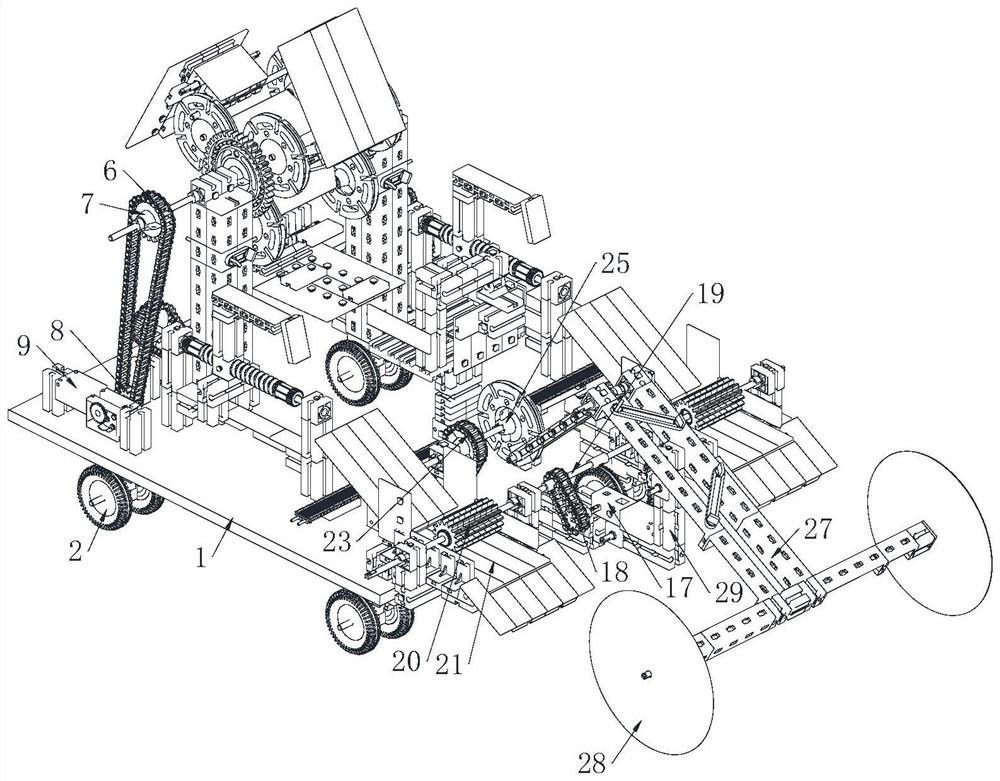
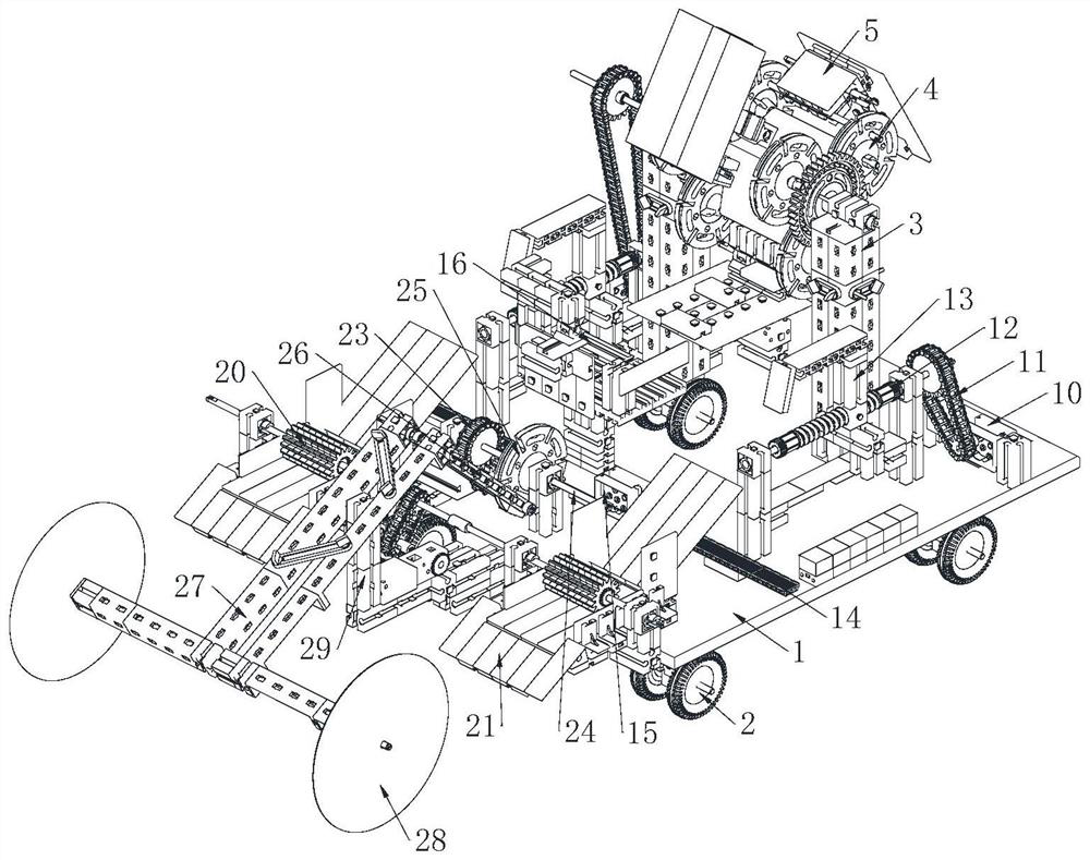
[0028] see Figure 1-6 As shown, the automatic grass grid laying machine includes a fixed base plate 1, a power wheel 2, a support frame 3 and a laying unit; the lower surface of the fixed base plate 1 is affixed with a plurality of power wheels 2; The surface is fixed with a support frame 3; the support frame 3 is provided with a laying unit; the laying unit includes a storage rack 4, a tumbleweed cover 5 and a first chain 6; the support frame 3 is rotatably connected with a storage frame 4; the storage rack 4 is rotatably connected with a plurality of tumbleweed covers 5; the storage rack 4 is fixedly connected with a first sprocket 7; the first sprocket 7 is meshed with a first chain 6; the lower end of the first chain 6 is meshed with a second sprocket 8; the second sprocket 8 is affixed to the first reduction motor 9; the upper surface of the fixed bottom plate 1 is symmetrically affixed with a second Geared motor 10; the output shaft of the second geared motor 10 is con...

Embodiment 2

[0037] see Figure 7 As shown in Comparative Example 1, as another embodiment of the present invention, the side of the sliding shaft 33 is fixed with a plurality of pins 36 at vertical intervals; Scraping, so as to realize the function of collecting, so as to realize the function of semi-automatically recovering the hay that has not been fixed, and it is convenient to remove the scraped hay. Cooperating with the sliding shaft 33, it can also move up and down with the sliding shaft 33, so as to adapt to different terrains .

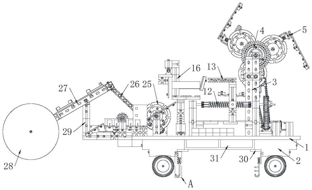
[0038] The working principle is to place the bundled grass rolls in the storage rack 4 and limit them to prevent falling through the rolling grass cover 5, and then drive the first chain 6 and the storage rack 4 to rotate through the first reduction motor 9, thereby realizing the cycle The feeding function, the feeding rack 16 pushes the feeding rack 16 to dock with the storage rack 4 through the push unit 15 made of the combination of the motor and the ...


PUM


Abstract

The invention belongs to the field of greening, and particularly relates to an automatic straw grid laying machine which comprises a fixed bottom plate, power wheels, a supporting frame and a laying unit. Bundled grass rolls are placed in the storage frame and limited by the grass rolling cover to be prevented from falling off, then the first chain and the storage frame are driven by the first gear motor to rotate, and therefore the circulating feeding function is achieved, the feeding frame is pushed to be in butt joint with the storage frame through the pushing unit formed by combining the motor and the gear, and the feeding efficiency is improved. When the storage rack rotates, the grass rolls enter the feeding rack under the action of gravity, then the feeding rack moves and is in butt joint with the discharging plate, the pushing rack is driven by the second gear motor to move in a reciprocating mode, the grass rolls are pushed to enter the discharging plate, the grass rolls in the discharging plate press the initial ends of the grass rolls which are rolled up clockwise under the clockwise rotation of the discharging pushing roller, and the grass rolls are conveyed to the feeding rack. Therefore, the function of automatically and efficiently laying hay is realized.

Description

technical field [0001] The invention relates to the field of greening, in particular to an automatic grass grid laying machine. Background technique [0002] The grass grid laying machine refers to the equipment that uses cylindrical haystack rolls to lay the haystacks in rolls, so as to achieve efficient coverage of the ground. [0003] Grass grids are a way to control deserts. It is necessary to use dry grass inserted into the soil to limit the movement of sandstorms, thereby reducing the occurrence of sand blowing and slowing down the movement of sand. [0004] Traditional grass grids are manually inserted into the soil, so laying grass grids in a large area requires a lot of manpower and tools. The manual laying method is inefficient and not suitable for laying grass grids in large areas; therefore, an automatic Grass grid laying machine. Contents of the invention [0005] In order to make up for the shortcomings of the existing technology, the traditional grass grid...

Claims


Application Information

Patent Timeline
Patent Type & Authority Applications(China)
IPC IPC(8): E02D3/00
Inventor 漆小敏孙俞泉孙永豪王静平姚朋晖李朝阳杜方杰
Owner ANHUI UNIVERSITY OF TECHNOLOGY AND SCIENCE
Why Eureka
Try Eureka