
Bathroom shower nozzle with pulsation disc

A technology of pulsating discs and nozzles, applied in the field of bathroom nozzles/showers/showers

Pending Publication Date: 2022-04-12
GROHE
View PDF4 Cites 0 Cited by
  • Summary
  • Abstract
  • Description
  • Claims
  • Application Information

AI Technical Summary

Problems solved by technology

However, the disadvantage of the sanitary shower head is that the jet pattern is only formed weakly at low liquid pressure

Method used


Image

  • Bathroom shower nozzle with pulsation disc
  • Bathroom shower nozzle with pulsation disc
  • Bathroom shower nozzle with pulsation disc

Examples


Embodiment Construction

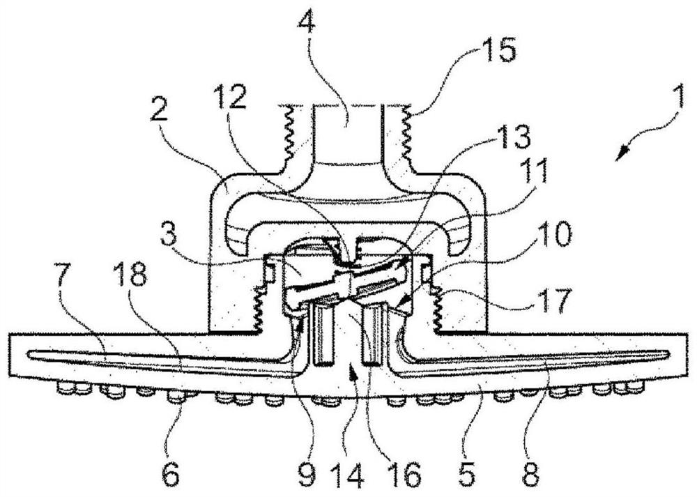
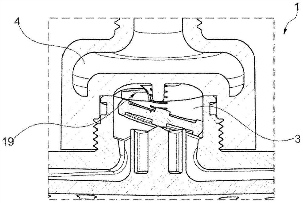
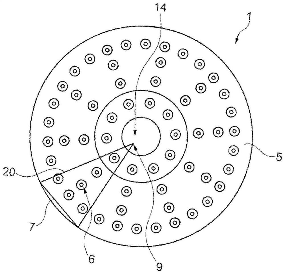
[0031] figure 1 The sanitary shower head 1 is shown in longitudinal section. The bathroom shower head 1 can be a hand-held shower head or an overhead shower head for showering. The sanitary shower head 1 comprises a housing 2, which here is designed as a flow-facing element type construction. Formed in the housing 2 is a delivery channel 4 for the liquid, which opens into the pulsation chamber 3 of the housing 2 . For the delivery of liquids, the housing 2 can be connected via a first thread 15 to a supply line (not shown here). Arranged in the pulsation chamber 3 is a pulsation disk 11 , which is supported at its center point 12 point-like on a support 16 and is pressed against the support 16 by a spring 13 . The housing 2 is connected to the jet former 5 via a second thread 17 . The jet former 5 has a plurality of discharge nozzles 6 assigned to chambers through which liquid can be delivered to the discharge nozzles 6 . A plurality of discharge nozzles 6 are assigned ...


PUM


Abstract

The invention relates to a bathroom shower head (1), at least comprising:-a housing (2) having at least one feed channel (4) for a liquid, said feed channel leading into a pulsation chamber (3); -a jet former (5) having a plurality of discharge nozzles (6) for the liquid; -a plurality of chambers (7, 8) which are connected to the pulsation chamber (3) via chamber inlets (9, 10), liquid being able to be conveyed through each of the chambers (7, 8) to at least one discharge nozzle (6) of the jet former (5); a pulsation disc (11) which is arranged in the pulsation chamber (3) and which can be moved by the liquid such that at least one of the chamber inlets (9, 10) can be alternately closed at least partially by the pulsation disc (11).

Description

technical field [0001] The invention relates to a shower head / shower head / shower for sanitary equipment accessories. Sanitation fittings are used in particular to provide liquids, especially water, on demand at sinks, washbasins, showers or bathtubs. Background technique [0002] The sanitary shower head for a plumbing fixture can be designed, for example, in the type of an overhead spray or a hand shower and / or can be used to distribute the liquid discharged through the plumbing fixture over a large area. The liquid can be discharged via the sanitary shower head in at least one jet form, for example in the form of a rain jet, a full jet or a pearl jet. However, a disadvantage of the shower head is that the jet pattern is only formed weakly at low liquid pressures. Contents of the invention [0003] It is therefore an object of the present invention to at least partly solve the problems described in the prior art, in particular to provide a sanitary shower head by which ...

Claims


Application Information

Patent Timeline
Patent Type & Authority Applications(China)
IPC IPC(8): B05B1/18B05B1/08
CPCB05B1/18B05B1/083B05B1/1636B05B3/04
Inventor S·弗拉格S·梅
Owner GROHE
Learn More