Breathing linkage device for aviation oxygen supply

A linkage device and oxygen supply technology, which is applied in the direction of respiratory protection devices, fire rescue, life-saving equipment, etc., can solve the problem of high cost, and achieve the effects of reducing loss, sealing reliability, and sealing stability

Active Publication Date: 2022-04-15
南通通易航天科技股份有限公司
View PDF9 Cites 0 Cited by
  • Summary
  • Abstract
  • Description
  • Claims
  • Application Information

AI Technical Summary

Problems solved by technology

However, after a period of use, it is impossible to ensure that the inspiratory diaphragm is completely blocked from oxygen entering the mask under pressure, requiring maintenance or direct replacement, and the cost is high

Method used


Image

  • Breathing linkage device for aviation oxygen supply
  • Breathing linkage device for aviation oxygen supply
  • Breathing linkage device for aviation oxygen supply

Examples


Embodiment 1

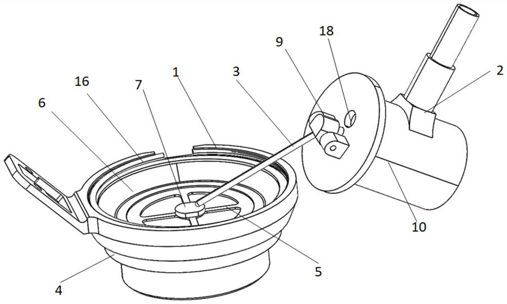
[0027] refer to Figure 1-8 , the present invention provides a technical solution, a respiratory linkage device for aviation oxygen supply, comprising a linked expiratory valve 1 and an inhalation module 2, and the linked exhalation valve 1 and the inhalation module 2 pass through a connecting rod 3 connections;

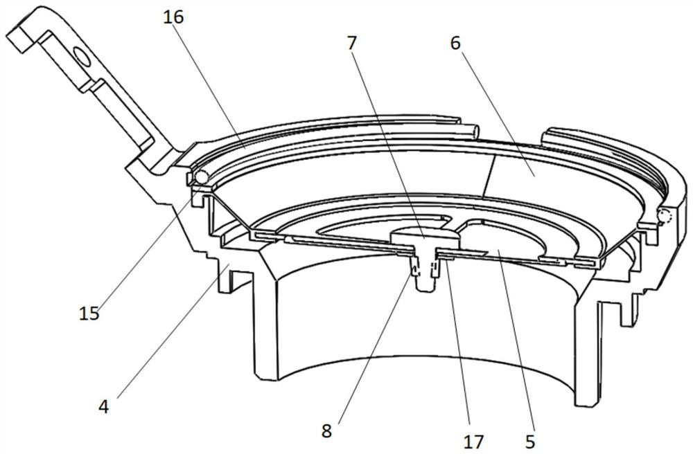
[0028] The linked exhalation valve 1 includes an exhalation base 4, an exhalation diaphragm 5 and an integrated diaphragm 6. The integral diaphragm 6 is arranged around the center of the exhalation base 4 and connected to the inner wall of the exhalation base 4. The exhalation diaphragm 5 is arranged on the inner side of the integral diaphragm 6 and connected with the inner wall of the integral diaphragm 6. The center of the expiratory diaphragm 5 is provided with a screw 7 and a lock nut 8. One end of the connecting rod 3 is connected to the top of the screw 7, and the bottom end of the screw 7 passes through Over-expiratory diaphragm 5 is connected with lock nut 8...

Embodiment 2

[0039] refer to Figure 1-8 , on the basis of Example 1:

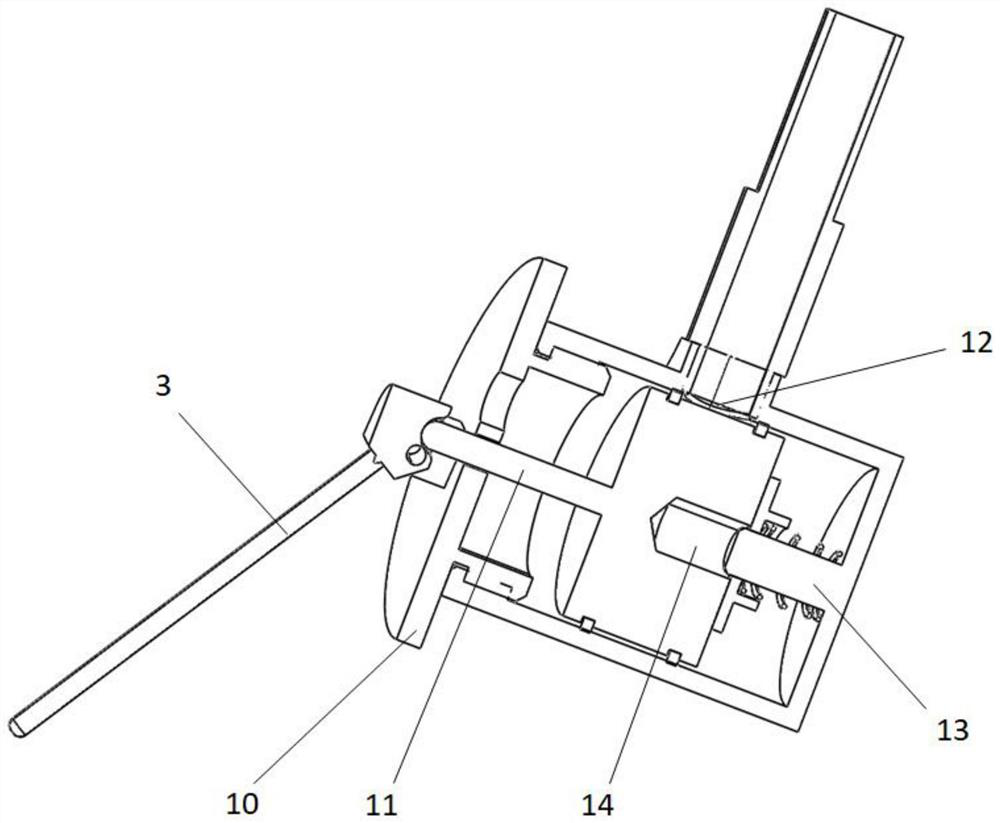
[0040] When there is a certain amount of oxygen in the cavity of the mask 20, slightly inhale, the cavity of the mask 20 is under a small negative pressure, which is affected by the pressure, such as Figure 4-5 , in the state of first-level lifting, the expiratory diaphragm 5 and the integrated diaphragm 6 in the interlocking exhalation valve 1 are lifted. At this time, the integrated diaphragm 6 is deformed, and the cross-section of the integrated diaphragm 6 is U Type, one end of the connecting rod 3 moves with the lifting of the screw 7, the other end of the connecting rod 3 drives the connecting rod seat 9 to rotate a small angle, the connecting rod seat 9 compresses the sealing shaft 11 in the suction module 2, and the sealing shaft 11 moves a certain distance , the air inlet 13 of the inhalation module 2 is in a half-open state, and oxygen enters the cavity of the face mask 20 through the half-open air inlet 13...


PUM


Abstract

The invention discloses a breathing linkage device for aviation oxygen supply, and belongs to the technical field of oxygen supply devices, the breathing linkage device comprises a linkage type expiration valve and an inspiration module, and the linkage type expiration valve is connected with the inspiration module through a connecting rod; the linkage type expiration valve comprises an expiration base, an expiration diaphragm and an integrated diaphragm, a screw and a locking nut are arranged in the center of the expiration diaphragm, one end of a connecting rod is connected with the top end of the screw, the inspiration module comprises a sealing shell, a sealing shaft is movably arranged in the sealing shell, one end of the sealing shaft extends out of the sealing shell and is connected with the other end of the connecting rod, and the integrated diaphragm is arranged in the sealing shell. An air inlet is formed in the sealing shell and is externally connected with an air source; opening and closing of an air inlet of the air suction module are controlled through a mechanical transmission structure, and the sealing performance of closing is more stable and reliable; the secondary oxygen supply structure can automatically adjust the oxygen supply amount according to the oxygen content in the cavity of the mask, unnecessary oxygen loss during expiration is reduced, and the oxygen waiting time is prolonged.

Description

technical field [0001] The invention belongs to the technical field of oxygen supply devices, and relates to a respiratory linkage device for aviation oxygen supply. Background technique [0002] The oxygen supply of the aviation oxygen supply surface is mainly through the cooperation of the inhalation base and the inhalation diaphragm. When inhaling, there is a negative pressure in the cavity of the mask, the sides of the inspiratory diaphragm are raised, and oxygen enters the mask; when exhaling, the cavity of the mask is positive pressure, the inspiratory diaphragm is pressed against the inspiratory base, and oxygen Barred from entering the mask. However, after a period of use, it is impossible to ensure that the inspiratory diaphragm is completely blocked from oxygen entering the mask under pressure, and maintenance or direct replacement is required, and the cost is relatively high. Contents of the invention [0003] The technical problem to be solved in the present ...

Claims


Application Information

Patent Timeline
Patent Type & Authority Applications(China)
IPC IPC(8): A62B7/14
CPCA62B7/14
Inventor 袁海云李申义施凯飞
Owner 南通通易航天科技股份有限公司
Why Eureka
Try Eureka