Elevator driving motor and brake cooperative control device and elevator
A driving motor and collaborative control technology, applied in the field of elevators, to achieve the effect of increasing passenger capacity, reducing the number of people waiting for elevators, and improving transportation efficiency
- Summary
- Abstract
- Description
- Claims
- Application Information
AI Technical Summary
Problems solved by technology
Method used
Image

Examples
Embodiment 1
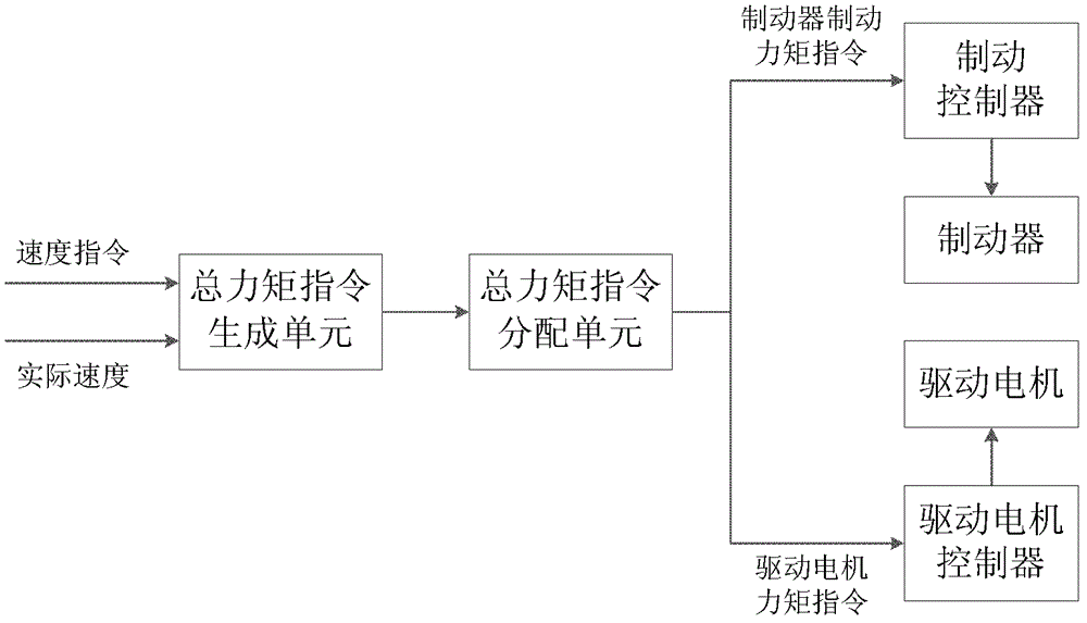
[0035] see figure 1The schematic diagram of the overall structure of the cooperative control device of the elevator driving motor and the brake of the present invention is shown. The cooperative control device of the elevator driving motor and the brake of the present invention includes: a driving motor that provides driving torque for the elevator car to rise and fall in the hoistway; The car lifts and lowers in the hoistway to provide braking torque and the brake torque can be controlled, and the total torque of the total torque command is generated according to the speed command of the driving motor or the car and the actual speed of the driving motor or car a command generation unit, which distributes the total torque command generated by the total torque command generation unit and generates the total torque command distribution unit of the drive motor torque command and the brake braking torque command, according to the total torque command distribution unit The generate...
Embodiment 2
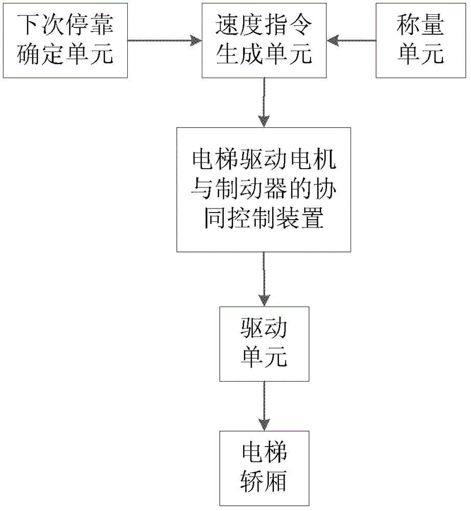
[0050] see figure 2 Shown is a schematic diagram of the overall structure of an elevator that uses a cooperative control device for an elevator drive motor and a brake in the present invention. It can be seen that the elevator includes a weighing unit for determining the load of the elevator car, and a weighing unit for determining the next stop floor of the elevator car. The next stop determination unit, the speed instruction generation unit for generating the elevator car to run from the current position to the next stop floor of the elevator car determined by the next stop determination unit, and the elevator drive motor and brake in Embodiment 1 cooperative control device. The next stop floor signal of the elevator car output by the next stop determination unit and the elevator car load signal output by the weighing unit are sent to the speed command generation unit as input signals, and the speed command generation unit is based on the input signal of the next stop of th...
Embodiment 3
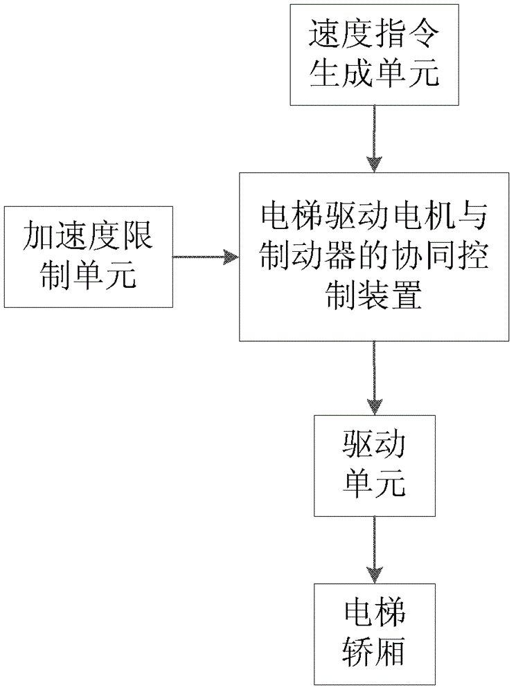
[0053] see image 3 Shown is a schematic diagram of the overall structure of another elevator that uses the cooperative control device of the elevator drive motor and brake in the present invention. It can be seen that the elevator includes a speed command generation unit for generating the speed command of the elevator car, and the elevator in Embodiment 1 The coordinated control device of the driving motor and the brake and the limit limiting torque determined by comparing the braking torque with the maximum torque that can be generated by the driving motor and the maximum braking torque that can be generated by the brake determine the car Acceleration limiting unit whether the acceleration reaches the limit limiting torque. The speed command signal output by the speed command generating unit and the acceleration limit value output by the acceleration limiting unit are sent to the cooperative control device of the elevator drive motor and brake as input signals, and the coop...
PUM
 Abstract
Description
Claims
Application Information
 - R&D
- Intellectual Property
- Life Sciences
- Materials
- Tech Scout
- Unparalleled Data Quality
- Higher Quality Content
- 60% Fewer Hallucinations
Browse by: Latest US Patents, China's latest patents, Technical Efficacy Thesaurus, Application Domain, Technology Topic, Popular Technical Reports.
© 2025 PatSnap. All rights reserved.Legal|Privacy policy|Modern Slavery Act Transparency Statement|Sitemap|About US| Contact US: help@patsnap.com