Auxiliary limiting stopper for clamp

A technology of stopper and fixture, applied in the direction of manufacturing tools, workpiece clamping devices, etc., can solve the problems of workpiece deformation, quality decline, affecting sales and use, etc., and achieve the effect of avoiding over-tightening and avoiding pinch injuries.

Pending Publication Date: 2022-04-15
浙江坤博精工科技股份有限公司
View PDF0 Cites 0 Cited by
  • Summary
  • Abstract
  • Description
  • Claims
  • Application Information

AI Technical Summary

Problems solved by technology

[0003] At present, when fixtures are used to clamp thin-plate-shaped injection molding workpieces with thin thickness and high processing accuracy requirements, the deformation of the workpiece is prone to occur, resulting in uneven thickness of each point of the workpiece and a decline in quality, which affects the later stage. The sale and use of

Method used


Image

  • Auxiliary limiting stopper for clamp
  • Auxiliary limiting stopper for clamp
  • Auxiliary limiting stopper for clamp

Examples


Embodiment 1

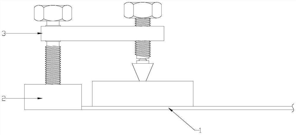
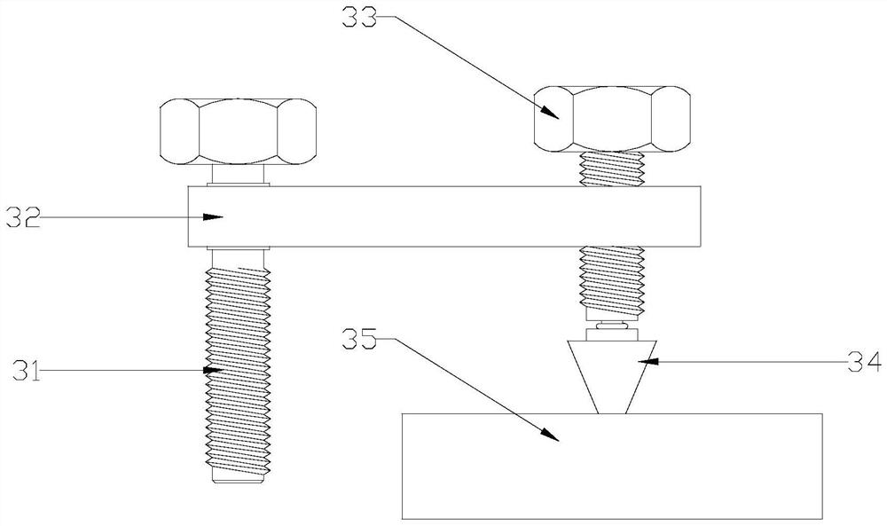
[0025] refer to Figure 1 to Figure 5 , an auxiliary limiter for clamps according to the present invention, including a positioning bolt 31, a support piece 32, a fastening bolt 33, a fastening block 34 and a fastening plate 35, the support piece 32 is arranged horizontally and one end is rotatably connected to the positioning The screw rod of the bolt 31 and the other end are screwed on the screw rod of the fastening bolt 33 , and the fastening block 34 is installed on the bottom end of the screw rod of the fastening bolt 33 and presses the top surface of the fastening plate 35 downward.

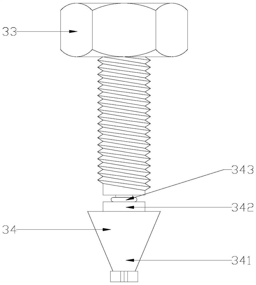
[0026] The fastening block 34 includes a terminal 341, a plug 342 and a spring 343. The bottom end of the screw rod of the fastening bolt 33 is provided with a blind hole 331, and the top end of the plug 342 is provided with a protrusion extending into the blind hole 331. strip 3421, the bottom end of the plug 342 is rotatably connected to the top end of the terminal 341, the spring 343 is ...

Embodiment 2

[0035] refer to Figure 1 to Figure 6 , also includes screw drive 36 and controller, and described screw drive 36 comprises nut 361, gear 362 and motor 363, and described nut 361 and gear 362 all can be rotatably connected in the support plate 32, on the outer wall of described nut 361 It is provided with teeth and meshes with the gear 362. The motor 363 is installed on the support plate 32 and drives the gear 362 to rotate. The screw of the fastening bolt 33 is threaded with the nut 361, and the screw driver 36 is connected with the controller. electrical connection.

[0036] A thickened portion 321 is provided at the place where the nut 361 is mounted on the support piece 32 .

[0037] A pressure sensor 37 is installed in the fastening plate 35, and the pressure sensor 37 is electrically connected with the controller.

[0038] Others are the same as embodiment one.

[0039] When the clamping block 341 extends into the notch, the motor 363 can be directly used to drive the...


PUM


Abstract

The auxiliary limiting stopper comprises a positioning bolt, a supporting piece, a fastening bolt, a fastening block and a fastening plate, the supporting piece is horizontally arranged, one end of the supporting piece is rotatably connected to a threaded rod of the positioning bolt, and the other end of the supporting piece is in threaded connection to a threaded rod of the fastening bolt; the fastening block is installed at the bottom end of a screw rod of the fastening bolt and presses the top face of the fastening plate downwards. The position of the limiting stopper is fixed through the positioning bolt, the fastening block is driven to move up and down through cooperation between the supporting piece and the fastening bolt, then under isolation of the fastening plate with the proper size, the acting pressure of the end is dispersed, and therefore the workpiece is effectively prevented from being damaged by clamping while the clamping effect is guaranteed.

Description

【Technical field】 [0001] The invention relates to the technical field of clamps, in particular to the technical field of an auxiliary limiter for a clamp. 【Background technique】 [0002] Injection molding machine, also known as injection molding machine or injection machine, is the main molding equipment for making thermoplastics or thermosetting plastics into various shapes of plastic products using plastic molding molds. It is divided into vertical, horizontal and all-electric types. Injection molding is to plasticize the plastic in the heating barrel of the injection molding machine, and then inject it into the cavity of the closed mold by a plunger or a reciprocating screw, thereby forming a plastic processing method of injection molded workpieces with complex shapes, precise dimensions, or inserts. . [0003] At present, when fixtures are used to clamp thin-plate-shaped injection molding workpieces with thin thickness and high processing accuracy requirements, the defo...

Claims


Application Information

Patent Timeline
Patent Type & Authority Applications(China)
IPC IPC(8): B25B11/00
Inventor 罗鑫磊厉伟
Owner 浙江坤博精工科技股份有限公司
Why Eureka
Try Eureka