Trolley convenient for unloading in building construction

A technology for building construction and trolleys, applied in the field of trolleys, can solve the problems of easy shaking of building materials and bumpy roads, etc., and achieve the effects of good cutting, improving work efficiency and preventing falling

Pending Publication Date: 2022-04-15
蔡政丽
View PDF10 Cites 1 Cited by
  • Summary
  • Abstract
  • Description
  • Claims
  • Application Information

AI Technical Summary

Problems solved by technology

[0005] In order to overcome the disadvantages that the trolleys used for building construction that are convenient for unloading cannot block the main body during the transportation of building materials, resulting in bumpy roads and easy shaking of building materials, the technical problem of the present invention is to provide a During the transportation of materials, the main body is blocked to prevent the construction materials from shaking out. The trolley for easy unloading of the building construction

Method used


Image

  • Trolley convenient for unloading in building construction
  • Trolley convenient for unloading in building construction
  • Trolley convenient for unloading in building construction

Examples


Embodiment 1

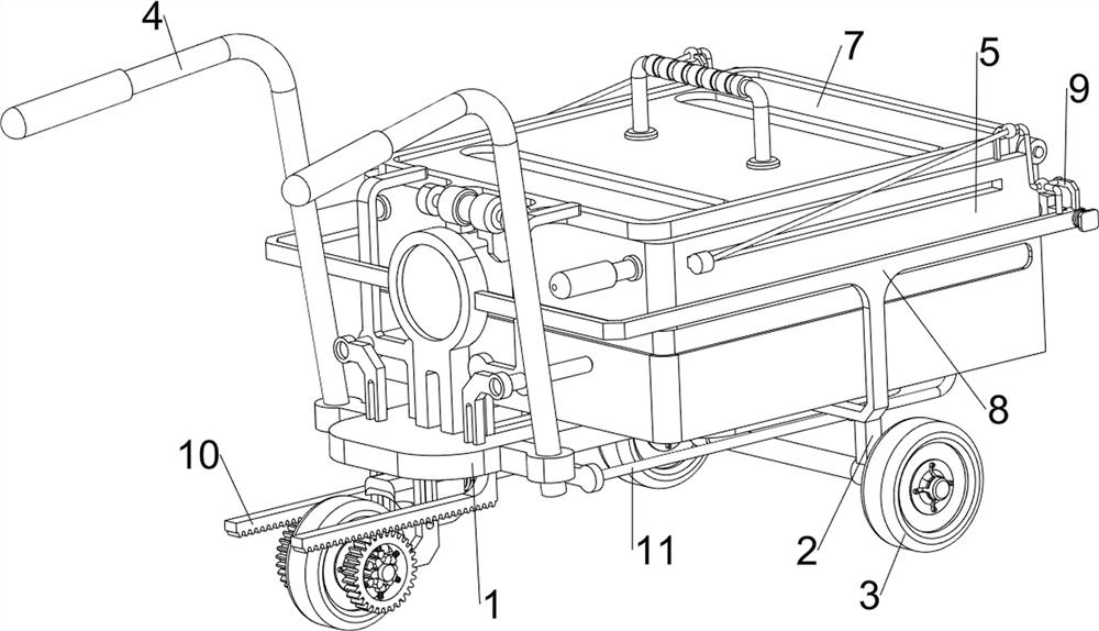
[0069] Trolley, reference for building construction facilitates unloading Figure 1 - Figure 4 As shown, including the placement plate 1, the first connecting block 2, the wheel 3, the first handle 4, the charge frame 5, the power mechanism 6, and the blocking mechanism 7, and the front and rear sides of the bottom right end of the place plate 1 are provided with a first connection block. 2. Two first connecting block 2 is provided with two wheel 3 by rotating the shaft rotation, the left end of the placing plate 1 is provided with a wheel 3 through the rotating shaft rotation, and the left end and rear on the top of the plate 1 are provided on both sides. The first handle 4, and the outer side of the two first hand 4 has a non-slip glove, so that when people come into contact with the first handle 4, it is possible to function as a non-slip, and the plate 1 is provided with a load frame 5, place the plate. 1 The power mechanism 6 is provided at the bottom, and the power mechanism ...

Embodiment 2

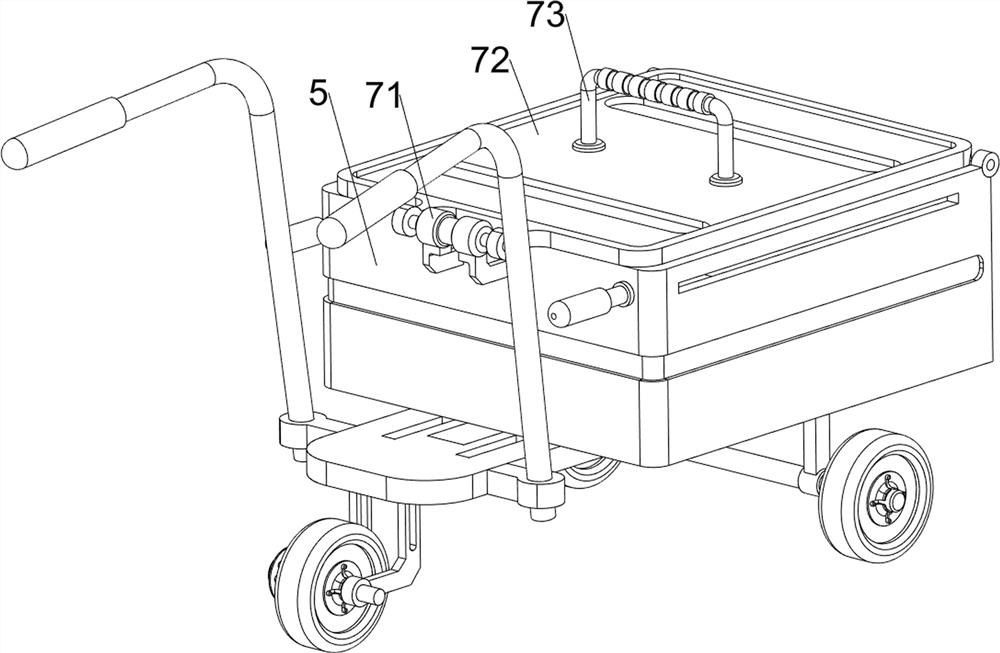
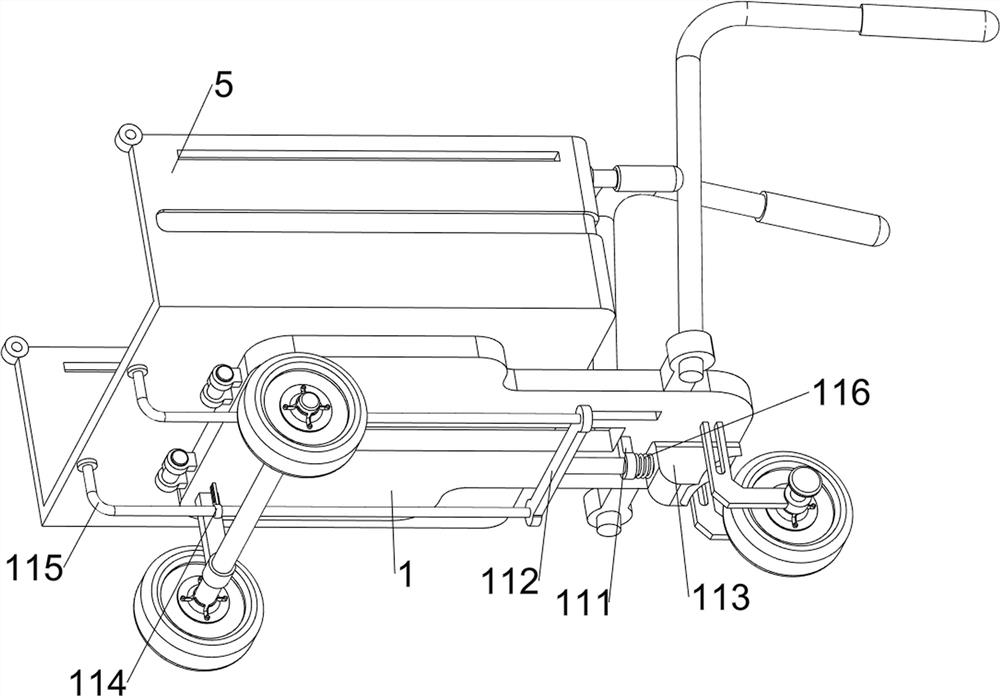
[0076] On the basis of Example 1, such as figure 1 , Figure 5 , Image 6 , Figure 7 , Figure 8 , Figure 9 , Figure 10 and Figure 11 As shown, it is also included, and the discharge mechanism 8 includes a rotating plate 81, a frame 82, a slide block 83, and a first reset spring 84. The right end rotation of the charge frame 5 is provided with a rotary plate 81, and the rotary plate 81 Adjust to the fitting frame 5, the left end of the plate 1 is provided with a frame 82, and the frame 82 is slidably equipped with a sliding block 83 on both sides, and the two sliding blocks 83 are in contact with the rotating plate 81, two sliding blocks 83. A first reset spring 84 is provided between the frame 82, and the two first reset spring 84 are respectively wrapped on the same side slide 83, respectively.

[0077] When the construction material is required, the sliding block 83 is needed to be pressed against the sliding block 83, so that the sliding block 83 moves outward, the first reset sp...


PUM


Abstract

The invention relates to a trolley, in particular to a trolley facilitating unloading in building construction. According to the trolley facilitating unloading in building construction, in the transportation process of building materials, the main body can be blocked, and the building materials are prevented from shaking out. A trolley facilitating unloading in building construction comprises a placing plate, first connecting blocks, wheels, a first handle and a loading frame, the first connecting blocks are arranged on the front side and the rear side of the right end of the bottom of the placing plate, the two wheels are rotationally arranged between the lower portions of the two first connecting blocks through rotating shafts, and the wheels are rotationally arranged at the left end of the bottom of the placing plate through rotating shafts. The telescopic rod of the air cylinder extends to drive the first fixing block to move towards the upper side, the first fixing block drives the loading frame to rotate, and the loading frame pours out the building materials, so that the building materials are automatically poured out, manual pouring out of the building materials is reduced, and the working efficiency can be improved.

Description

Technical field [0001] The present invention relates to a trolley, in particular, to a trolley for construction facilities for unloading. Background technique [0002] Building construction takes a trolley in a building construction site, generally includes a vehicle, car fighting, and two wheels with shaft support. Such a trolley can only be applied to carrying sand, stone solid materials, if necessary The material is unloading, and the worker is required to turn the car, the unloading is very inconvenient, and it is time consuming. [0003] Patent application CN210554881U, the public day is 20200519, which discloses a truck for facilitating unloading of construction, including a body and a bidirectional bolt, and a fixed bar is provided, and the fixed rod is penetrated, and the rotating shaft The engagement of the main body is connected to the roller, and the upper rear end of the main body is provided with a bracket and handle, and the handle is disposed above the bracket, and...

Claims


Application Information

Patent Timeline
Patent Type & Authority Applications(China)
IPC IPC(8): B62B3/04B62B3/08B62B5/04
Inventor 蔡政丽
Owner 蔡政丽
Why Eureka
Try Eureka