Subway entrance and exit line flood gate system
A flood-proof door, entry and exit technology, applied in the direction of anti-war damage, sealing devices, etc., can solve the problem of flood-proof doors without any water barriers, and achieve the effect of improving rapid response capabilities
- Summary
- Abstract
- Description
- Claims
- Application Information
AI Technical Summary
Problems solved by technology
Method used
Image
Examples
Embodiment 1
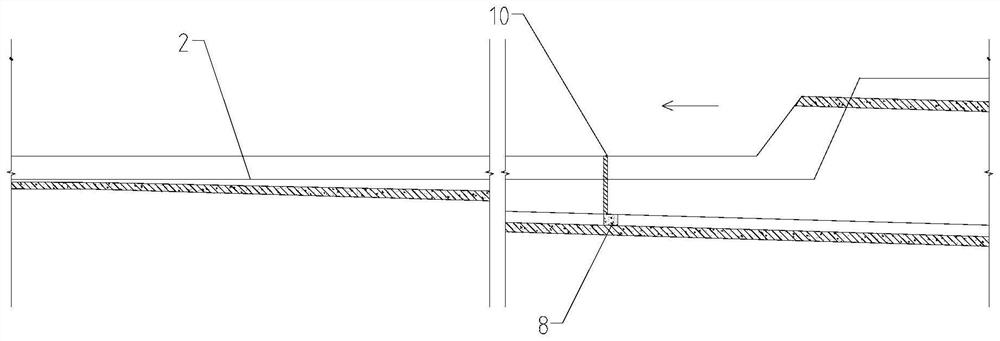
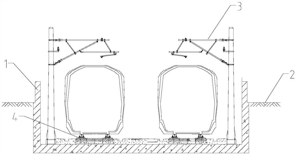
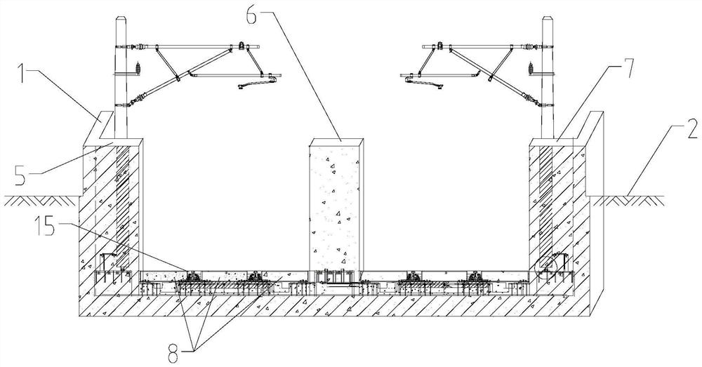
[0034] An anti-flooding door system for subway entry and exit lines, comprising a retaining wall 1, a first door stack 5, a second door stack 6, a third door stack 7, a rail crossing threshold 8 and an anti-flooding door 10.
[0035] Two rows of water retaining walls 1 are arranged on the outside of the two-way track 4 along the extension direction of the track 4, and the water retaining walls 1 are 1.2 meters above the ground 2 in the site. The water retaining wall 1 is formed by raising the side wall of the U-shaped groove section. The water retaining wall on the side wall of the U-shaped trough is 1.2m higher than the elevation of the parking lot pad (the ground in the site), and the parking lot pad is generally at least 0.5m higher than the flood control elevation of the surrounding area, so the anti-flooding door and the U The water retaining wall, door stack, and rail threshold on the side wall of the groove form a flood prevention capacity of at least 1.7m.
[0036] Th...
Embodiment 2
[0040]The difference between this embodiment and Embodiment 1 is that the sides of the two anti-flooding doors 10 are respectively installed on the door frame walls on the front sides of the first door stack 5 and the third door stack 7 . Several sets of installation components of the anti-flooding door 10 include a limit door shaft 101 , a wall embedded steel plate 102 , a butterfly positioner 103 , a limit shaft cylinder 104 and a sealing pin 105 . A plurality of butterfly positioners 103 are fixed parallel to the surface of the pre-embedded steel plate 102 on the wall, and a limit shaft cylinder 104 is vertically fixed in the positioning holes of the butterfly positioners 103 corresponding up and down. The bent section of the limit door shaft 101 is fixed to the side of the floodproof door 10 , and the vertical section of the limit door shaft 101 is inserted into the limit shaft cylinder 104 . A pin hole is defined at the end of the limiting door shaft 101 extending out of ...
Embodiment 3
[0042] The difference between this embodiment and Embodiment 2 is that the door shaft pile 9 is arranged at the bottom of the door frame wall, and the door shaft pile 9 includes a pile base 91 , a pre-embedded steel plate 92 , a door shaft support 93 and a bottom door shaft 94 . The upper surface of the pile seat 91 is fixedly embedded in the embedded steel plate 92, the door shaft support 93 is fixed on the embedded steel plate 92, and the bottom door shaft 94 of the anti-flooding door 10 is rotatably installed in the door shaft support 93. The height of the bottom pile 91 is flush with the height of the rail crossing threshold 8 .
PUM
 Abstract
Description
Claims
Application Information
 - R&D
- Intellectual Property
- Life Sciences
- Materials
- Tech Scout
- Unparalleled Data Quality
- Higher Quality Content
- 60% Fewer Hallucinations
Browse by: Latest US Patents, China's latest patents, Technical Efficacy Thesaurus, Application Domain, Technology Topic, Popular Technical Reports.
© 2025 PatSnap. All rights reserved.Legal|Privacy policy|Modern Slavery Act Transparency Statement|Sitemap|About US| Contact US: help@patsnap.com


