
Data-driven rotor system typical fault automatic identification method

A typical fault, data-driven technology, applied in the field of fault identification, can solve problems such as inability to accurately identify fault characteristics, and achieve the effect of reducing data modeling time and complexity

Pending Publication Date: 2022-04-15
BEIJING UNIV OF CHEM TECH
View PDF0 Cites 1 Cited by
  • Summary
  • Abstract
  • Description
  • Claims
  • Application Information

AI Technical Summary

Problems solved by technology

At this time, statistical feature parameter extraction based on signal processing can hardly identify fault features accurately

Method used


Image

  • Data-driven rotor system typical fault automatic identification method
  • Data-driven rotor system typical fault automatic identification method
  • Data-driven rotor system typical fault automatic identification method

Examples


Embodiment Construction

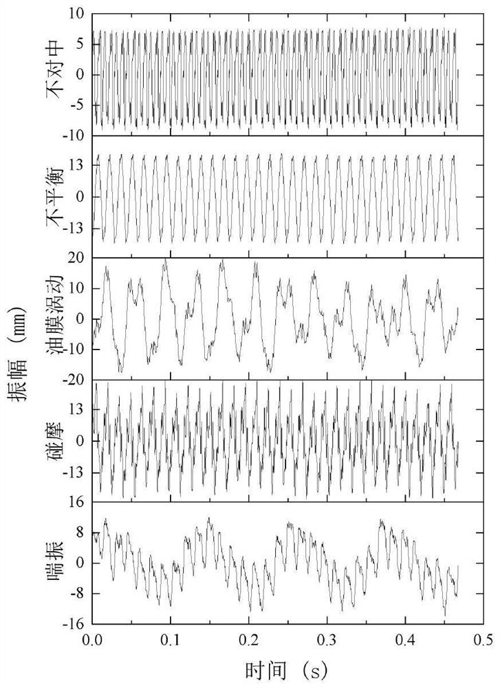
[0048] In order to describe the above process in detail, taking the typical fault label data of a company's real centrifugal compressor, steam turbine, and flue gas turbine rotor system as an example, select shaft misalignment, rotor unbalance, The data of five typical fault cases of oil film whirl, rubbing and surge are used as training data. The description of the training data is shown in Table 1. There are 150 sets of data for each type of fault state, and a total of 750 sets of data are used as training sets.

[0049] Table 1. Training dataset description

[0050]

[0051]

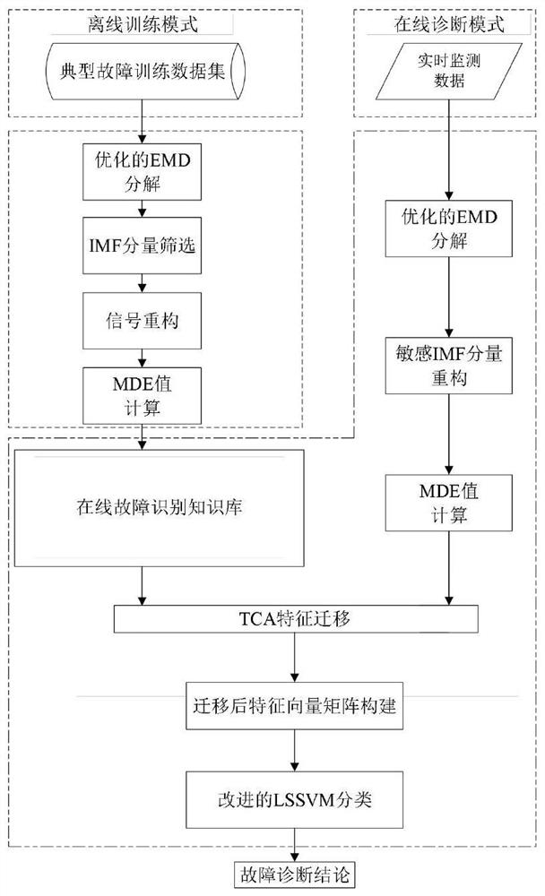
[0052] (1) adaptively determine the value of parameter K by ABC algorithm;

[0053] (2) Using the EMD method to decompose the rotor system diagnostic signal into a series of IMF components;

[0054] (3) Screening sensitive IMF component reconstruction through sensitive IMF component evaluation index;

[0055] (4) Calculate the 15 scale MDE values ​​of the reconstructed signal;

[0056] (5) C...


PUM


Abstract

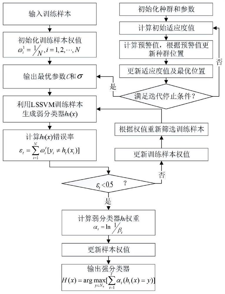
The invention discloses a typical fault automatic identification method for a data-driven rotor system. An offline training module, a fault classification knowledge base module and an online fault automatic identification module are included. Adaptively decomposing the original vibration waveform signal into a series of intrinsic mode function components by adopting optimized empirical mode decomposition; a feature conjoint analysis method is proposed to screen sensitive IMF components for signal reconstruction, and a multi-scale dispersion entropy value calculated by a reconstructed signal is screened as a feature value; constructing an LSSVM classifier to adaptively determine a penalty factor C and a kernel parameter sigma; the distance between the source domain data and the target domain data is minimized through transfer learning, a constructed transfer feature vector matrix serves as the input of a model, and fault mode recognition of the rotor system is achieved. According to the method, the original time sequence vibration waveform data is adopted as input, the fault identification conclusion can be automatically output, and the method has high identification accuracy and good generalization for rotor system fault data under different equipment and different working conditions.

Description

technical field [0001] The invention relates to an automatic fault identification method for a rotor system, in particular to a data-driven automatic identification method for a typical fault of a rotor system, and belongs to the technical field of fault identification. Background technique [0002] The rotor system is the core part of the rotating machinery. Once it fails, it will directly affect the working status of the entire rotating machinery, and even cause shutdown or equipment damage accidents. Therefore, in-depth study of the fault mode recognition technology of the rotor system is of great significance to ensure the safe operation of rotating machinery and eliminate accidents. There are many types of faults in the rotor system of rotating machinery, and the typical faults mainly include: shaft misalignment, rotor unbalance, oil film whirl, dynamic and static rubbing, surge and other faults. At present, many rotor system condition monitoring systems and fault diag...

Claims


Application Information

Patent Timeline
Patent Type & Authority Applications(China)
IPC IPC(8): G06K9/00G06K9/62
CPCG06F2218/08G06F2218/12G06F18/214
Inventor 肖扬王庆锋王帅
Owner BEIJING UNIV OF CHEM TECH
Learn More