Internal medicine pressing hemostasis device
A technology of internal medicine and airbag belt, applied in tourniquet, medical science, surgery, etc., can solve the problems of prolonging the duration of wound pain, tissue damage, prolonging the period of wound self-healing, etc., to avoid secondary damage.
- Summary
- Abstract
- Description
- Claims
- Application Information
AI Technical Summary
Problems solved by technology
Method used
Image

Examples
Embodiment Construction
[0029] In order to enable those skilled in the art to better understand the technical solutions of the present invention, the present invention will be further described in detail below in conjunction with the accompanying drawings.
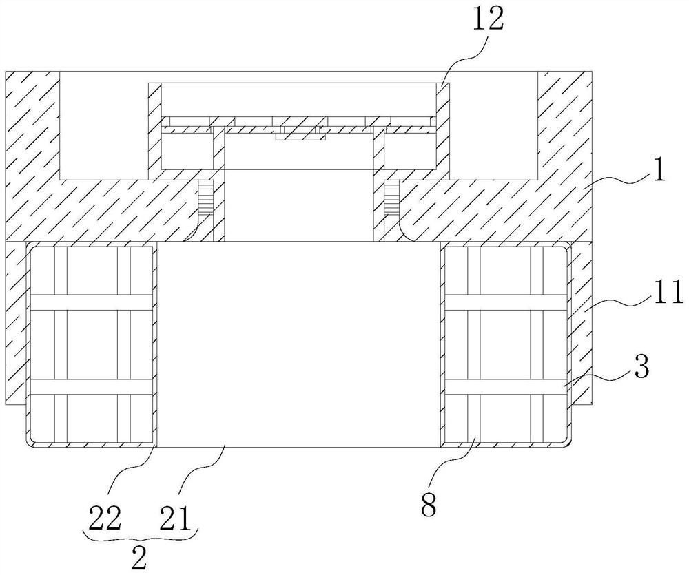
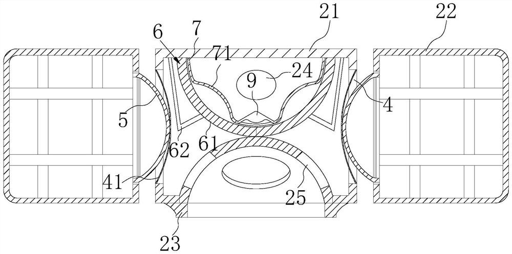
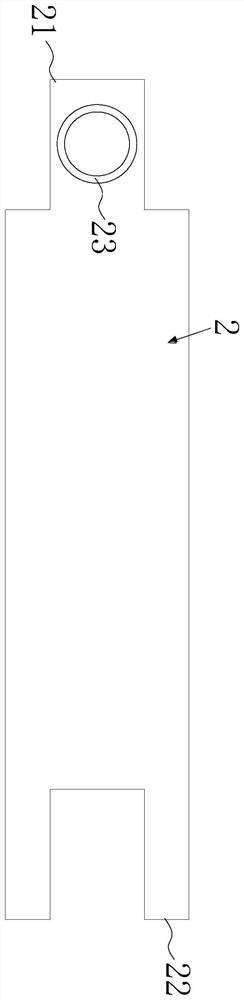
[0030] Such as Figure 1-4 As shown, a compression hemostasis device for internal medicine includes an air nozzle seat 1 and an air bag belt 2. One end of the air bag belt 2 is fixed on the air valve seat 1, and the other end wraps around the wrist arm and is fixed on the air valve seat 1 to form a circular shape. structure;
[0031] The airbag belt 2 is provided with a grid-shaped elastic rib frame, which is limited by the pulling of the grid-shaped elastic rib frame, so that the airbag belt 2 expands in a circular structure;
[0032] The air nozzle seat 1 is connected with an external inflatable device, so that the inside of the air bag belt 2 inflated in a circular structure maintains a predetermined air pressure for squeezing the wound to st...
PUM
 Abstract
Description
Claims
Application Information
PatSnap Eureka turns technology decisions into work you can execute. Powered by our Innovation Knowledge Graph, it runs expert workflows across engineering, life sciences, materials and intellectual property. Get your review-ready output in minutes.


