Supercharge Your Innovation With Domain-Expert AI Agents!

Automatic glove machine for wearing sterile gloves

A glove machine and automatic technology, applied in the field of machinery, can solve the problems of glove curling, exposing the mouth, increasing the workload of equipment nurses, etc., to achieve the effects of improving hygiene and safety, reducing contact area, and reducing bacterial infection

Inactive Publication Date: 2022-04-19
潍坊眼科医院有限责任公司
View PDF0 Cites 0 Cited by
  • Summary
  • Abstract
  • Description
  • Claims
  • Application Information

AI Technical Summary

Problems solved by technology

[0002] Strict aseptic technique is an effective measure to prevent incision infection and is also the key to ensure the quality of surgery and patient safety. Wearing sterile gloves is the first step to prevent surgical infection, which belongs to the basic aseptic operation in the operating room. In clinical practice, The traditional method of wearing sterile gloves has its own shortcomings. When the fingers are inserted into the glove, the edge of the glove is prone to curling, which may cause the sterile surface on the back of the surgeon's sterile gloves to be different from the sterile back of the hand. Contamination caused by skin contact; surgeons often cannot achieve the effect of maximizing the wrapping area between sterile gloves and sleeves in order to avoid contact with the edge skin of the contralateral cuff during the operation, which will cause friction during the operation. Or excessive stretching causes the wrist of the sterile glove to reverse or slide down, exposing the relatively polluted mouth and increasing the chance of infection during the operation: during the clinical work, the instrument nurse has to pull off the cuff of the sterile glove, and the surgeon puts it on. Invisibly increased the workload of equipment nurses, affecting the normal operation of the operation

Method used


Image

  • Automatic glove machine for wearing sterile gloves
  • Automatic glove machine for wearing sterile gloves
  • Automatic glove machine for wearing sterile gloves

Examples


Embodiment 1

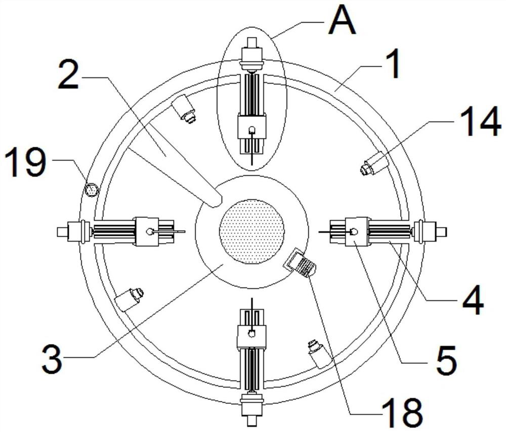
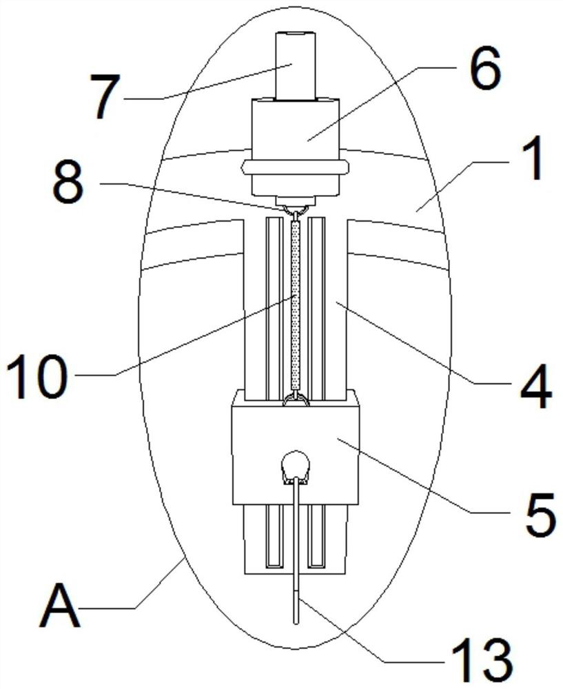
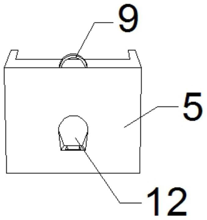
[0021] as Figure 1-6 As shown, an automatic glove machine for sterile glove wearing, comprising an mounting ring 1, a slide rail 4, a slider 5, an S-type pull hook 13 and a atomized sprinkler 14, the mounting ring 1 inner ring distribution fixed welding is provided with four sets of slide rails 4, the slide rail 4 on the sliding connection is connected to the slider 5, the slide rail 4 is located at one end and located on the mounting ring 1 is fixed with an electromagnet 6, the electromagnet 6 is inserted with a corresponding core 7, the core 7 is fixed at one end is provided with a first clasp 8, the slider 5 is fixed at one end is provided with a second clasp 9, The slider 5 side is provided with a buckle groove 12, the buckle groove 12 fixed hook 13, the mounting ring 1 bottom end fixed welding provided with a support rod 2, the support rod 2 bottom welding connection base 3, the mounting ring 1 inner ring and located between the slide rail 4 distributed there is a fogging noz...

Embodiment 2

[0030] as Figure 1-6 As shown, an automatic glove machine for sterile glove wearing, comprising an mounting ring 1, a slide rail 4, a slider 5, an S-type pull hook 13 and a atomized sprinkler 14, the mounting ring 1 inner ring distribution fixed welding is provided with four sets of slide rails 4, the slide rail 4 on the sliding connection is connected to the slider 5, the slide rail 4 is located at one end and located on the mounting ring 1 is fixed with an electromagnet 6, the electromagnet 6 is inserted with a corresponding core 7, the core 7 is fixed at one end is provided with a first clasp 8, the slider 5 is fixed at one end is provided with a second clasp 9, The slider 5 side is provided with a buckle groove 12, the buckle groove 12 fixed hook 13, the mounting ring 1 bottom end fixed welding provided with a support rod 2, the support rod 2 bottom welding connection base 3, the mounting ring 1 inner ring and located between the slide rail 4 distributed there is a fogging noz...


PUM


Abstract

The automatic glove machine comprises a mounting ring, sliding rails, sliding blocks, S-shaped drag hooks and atomizing nozzles, four sets of sliding rails are fixedly welded to the inner ring of the mounting ring in a distributed mode, the sliding blocks are slidably connected to the sliding rails, electromagnets are fixedly installed at the positions, located on the mounting ring, of one ends of the sliding rails, and the other ends of the sliding rails are fixedly connected with the S-shaped drag hooks. A corresponding iron core is inserted into the electromagnet, a first retaining ring is fixedly arranged at one end of the iron core, a second retaining ring is fixedly arranged at one end of the sliding block, a buckling groove is formed in one side of the sliding block, an S-shaped drag hook is fixedly hung and buckled on the buckling groove, a supporting rod is fixedly welded to one end of the bottom of the mounting ring, and a connecting base is welded to the bottom of the supporting rod. Atomizing nozzles are distributed and mounted on the inner ring of the mounting ring and located between the sliding rails, and a mounting groove is formed in one side in the base. The contact area is greatly reduced, the danger caused by exposed skin of a surgeon is greatly reduced, the probability of infection in an operation is reduced, and meanwhile the sterile concept of the surgeon on the operation is strengthened.

Description

Technical field [0001] The invention belongs to the field of mechanical technology, and specifically relates to an automatic glove machine for donning sterile gloves. Background technique [0002] Strict aseptic technique is an effective measure to prevent incisional infection and is the key to ensuring surgical quality and patient safety. Wearing sterile gloves is the first step to prevent surgical infection and is a basic aseptic operation in the operating room. In clinical practice, The traditional method of wearing sterile gloves has its own shortcomings. When fingers are inserted into the gloves, the edges of the gloves are prone to curling, causing the sterile surface on the back of the surgeon's sterile gloves to be in contact with the sterile back of the hand. Contamination is caused by the contact of the skin; in order to avoid contact with the edge skin of the contralateral cuff during the operation, the surgeon often cannot maximize the wrapping area between the s...

Claims


Application Information

Patent Timeline
IPC IPC(8): A61B42/50A61M11/00A61M35/00A61L2/22
CPCA61B42/50A61M11/00A61M35/20A61L2/22A61M2210/04A61M2210/005
Inventor 赵春峰喻文倩宋伟
Owner 潍坊眼科医院有限责任公司
Features
  • R&D
  • Intellectual Property
  • Life Sciences
  • Materials
  • Tech Scout
  • Unparalleled Data Quality
  • Higher Quality Content
  • 60% Fewer Hallucinations
Learn More