Front underbody structure of vehicle with improved stiffness

A front lower part, vehicle technology, applied in the direction of the substructure, upper structure, vehicle components, etc., can solve the problems of unfavorable stiffness in the front and rear directions

Pending Publication Date: 2022-04-19
HYUNDAI MOTOR CO LTD +1
View PDF0 Cites 0 Cited by
  • Summary
  • Abstract
  • Description
  • Claims
  • Application Information

AI Technical Summary

Problems solved by technology

However, this is disadvantageous for securing the stiffness in the front-rear direction

Method used


Image

  • Front underbody structure of vehicle with improved stiffness
  • Front underbody structure of vehicle with improved stiffness
  • Front underbody structure of vehicle with improved stiffness

Examples


Embodiment Construction

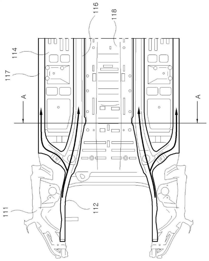
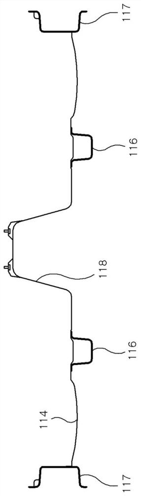
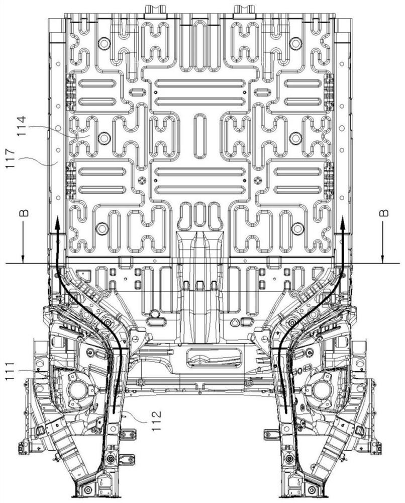
[0033] Hereinafter, a front underbody structure of a vehicle having improved rigidity according to an embodiment of the present invention will be described in detail with reference to the accompanying drawings.

[0034] Such as Figure 8-Figure 13 As shown, the front lower body structure of a vehicle having improved rigidity according to an embodiment of the present invention includes: a front side rear lower member 13, a center floor side upper member 15 and a reinforcement bracket 22, the front side rear lower member The front side member 12 formed on one side of the fender 11 is connected to the side member interior 17; the center floor side upper member 15 is formed in the longitudinal direction of the vehicle so as to extend from the upper surface of the dash panel 21 to the center floor panel 14 ; the reinforcement bracket 22 connects the front rear lower member 13 with the central floor upper member 15 .

[0035] The front lower body structure of the vehicle according ...


PUM


Abstract

A front lower body structure of a vehicle having improved rigidity includes a front side rear lower member connected to a side member inside from a front side member disposed on one side of a fender, a center floor side upper member, and a reinforcing bracket; a center floor side upper member disposed in a longitudinal direction of the vehicle and extending from an upper surface of the dash panel to the center floor panel; the reinforcing bracket connects the front side rear lower member with the central floor side upper member.

Description

technical field [0001] The present invention relates to a front underbody structure of a vehicle having improved stiffness. Background technique [0002] Such as figure 1 and figure 2 As shown, a vehicle equipped with an internal combustion engine distributes the load from the front side member 112 of the fender 111 towards the center floor panel 114 to the center floor side member 116 and the side member inner 117 to transmit the load to the rear side thereof (see figure 1 arrow shown in ). The load input to the front side member 112 is distributed to the center floor side member 116 and the side member inner 117 and transmitted to the rear of the vehicle, thereby ensuring sufficient rigidity against a collision. In addition, a vehicle mounted with an internal combustion engine is formed with a center tunnel 118 so that the center floor panel 114 has an exhaust pipe or the like mounted on a middle portion thereof, thereby also serving to improve rigidity. [0003] Howe...

Claims


Application Information

Patent Timeline
Patent Type & Authority Applications(China)
IPC IPC(8): B62D25/20B62D25/08
CPCB62D25/2018B62D25/08B62D21/15B62D25/2036B62D27/023B62D25/2009B62D25/2072B62D27/02B60Y2200/91B60Y2306/01B60Y2306/09B60Y2410/124
Inventor 金彦杓宋承泰
Owner HYUNDAI MOTOR CO LTD
Why Eureka
Try Eureka