
Antitheft warning photoelectric fence

A fence, photoelectric technology, applied in the direction of anti-theft alarm, anti-theft alarm mechanical start, fence and other directions, can solve the problems of unfavorable installation positioning and wiring, unfavorable accurate and efficient management, lack of safety and anti-theft structure, etc., to improve safety and anti-theft effect. , Conducive to timely alarm, improve the effect of control stability

Inactive Publication Date: 2022-04-19
山东汇久石油装备有限公司
View PDF0 Cites 0 Cited by
  • Summary
  • Abstract
  • Description
  • Claims
  • Application Information

AI Technical Summary

Problems solved by technology

[0003] However, in the existing photoelectric fence structure, the receiver and the transmitter are mostly installed directly through fixed vertical poles, and the photoelectric signal is transmitted between each other to form a fence structure. Such a structure is not only not conducive to installation positioning and arrangement Wires affect the power connection, and the receiver is fixedly installed. The mutual time needs to be installed at a fixed angle and position. It cannot be interchanged and adjusted. Accurate and efficient management, needs to be improved

Method used


Image

  • Antitheft warning photoelectric fence
  • Antitheft warning photoelectric fence
  • Antitheft warning photoelectric fence

Examples


Embodiment Construction

[0031] The following will clearly and completely describe the technical solutions in the embodiments of the present invention in conjunction with the accompanying drawings in the embodiments of the present invention; obviously, the described embodiments are only part of the embodiments of the present invention, not all embodiments, based on The embodiments of the present invention and all other embodiments obtained by persons of ordinary skill in the art without making creative efforts belong to the protection scope of the present invention.

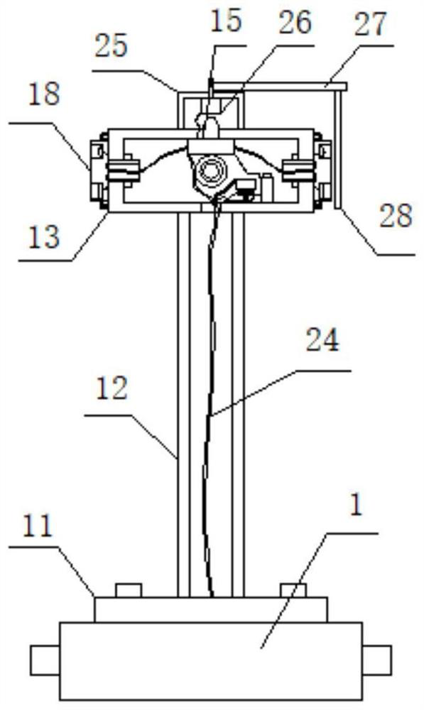
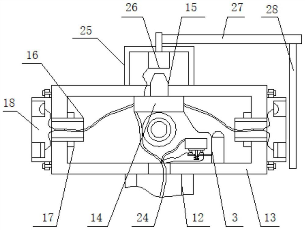
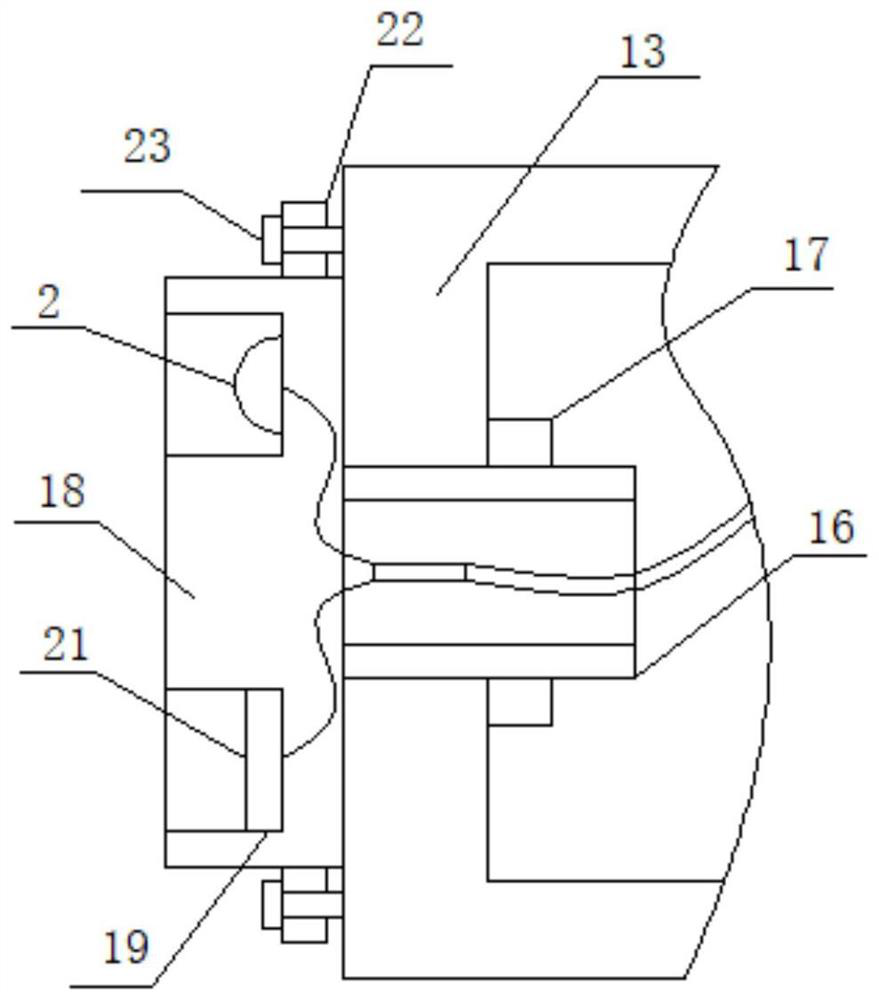
[0032] see Figure 1-4 , a photoelectric fence for anti-theft warning, including a fixed box 1, please refer to figure 2 and image 3 , one end surface of the fixed box body 1 is fixedly connected with a fixed seat 11, which can be pre-embedded in the bottom line, which is convenient for wiring connection and convenient installation and use. One side surface of the fixed seat 11 is fixedly connected with a fixed tube 12, and one end su...


PUM


Abstract

The invention discloses an anti-theft warning photoelectric fence which comprises a fixed box body, a fixed seat is fixedly connected to the surface of one end of the fixed box body, a fixed pipe is fixedly connected to the surface of one side of the fixed seat, an installation box body is fixedly installed on the surface of one end of the fixed pipe, and a control panel is fixedly installed on the surface of one side of the installation box body. An antenna is fixedly mounted on the surface of one side of the control panel, rotating pipes are rotatably mounted on the four surfaces of the mounting box body, a limiting ring is fixedly connected to the surface of one end of each rotating pipe, an adjusting disc is fixedly connected to the surface of the other end of each rotating pipe, and mounting grooves are formed in the two ends of the surface of one side of each adjusting disc; and a photoelectric emission head is fixedly mounted on the surface of one side of the mounting groove, and a photoelectric receiving block is fixedly mounted on the surface of the other side of the mounting groove, so that the use convenience and stability can be greatly improved, and the safety protection and anti-theft effects are ensured.

Description

technical field [0001] The invention relates to the field of photoelectric fences, in particular to a photoelectric fence for anti-theft warning. Background technique [0002] In oilfield projects, in order to strengthen on-site management and safety, it is necessary to install fences around the work site, which can be used for isolation and alarm reminders, which is conducive to timely handling of foreign personnel and animals to ensure safety. In order to avoid affecting construction and operation, more It is a fence structure using photoelectric signals. [0003] However, in the existing photoelectric fence structure, the receiver and the transmitter are mostly installed directly through fixed vertical poles, and the photoelectric signal is transmitted between each other to form a fence structure. Such a structure is not only not conducive to installation positioning and arrangement Wires affect the power connection, and the receiver is fixedly installed. The mutual time...

Claims


Application Information

Patent Timeline
IPC IPC(8): E04H17/00E04H17/20E04H17/22G08B13/12
CPCE04H17/00E04H17/20E04H17/22G08B13/124E04H17/017
Inventor 巴洪梅齐书杰张力杰
Owner 山东汇久石油装备有限公司
Learn More