


Quick Research
Generate reliable direction feasibility study reports for your R&D in just a few steps.

Technical Q&A
Discover and master advanced knowledge NOW. Basics, ideas, possibilities, all at once.

Find Solutions
As an expert in R&D theories, this can generate solutions to your technical problems instantly.

Evaluate Feasibility
Analyze your overall solution with one click, know your potential R&D risks in advance.

Monitor Landscape
Get weekly tech updates, stay abreast of the latest tech innovations and key insights.
Movable liquid collecting equipment for gynecological hysteroscopic surgery
A collection equipment and hysteroscope technology, which is applied in the fields of surgery, medical science, disinfection, etc., can solve the problems of inconvenient collection of uterine distention fluid, and achieve the effect of convenient collection and convenient movement
- Summary
- Abstract
- Description
- Claims
- Application Information
AI Technical Summary
Problems solved by technology
Method used
Image

Examples
Embodiment 1
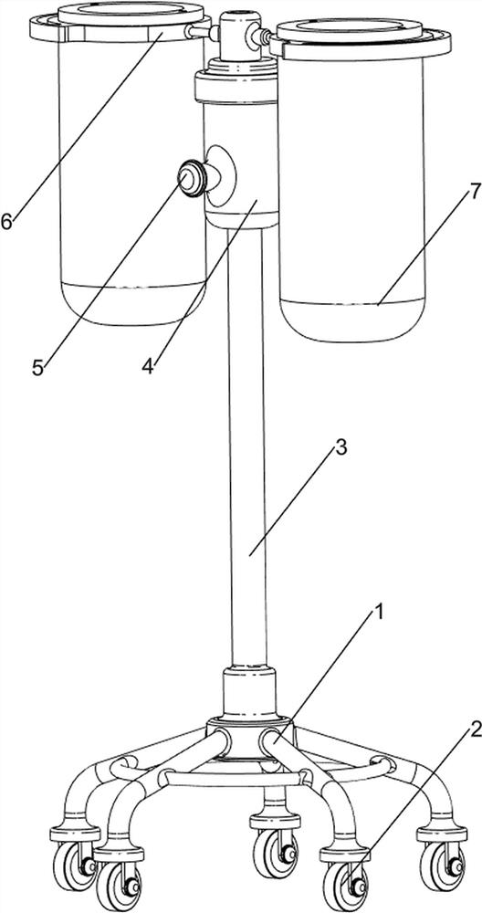
[0030] A liquid movable collection device for gynecological hysteroscopic surgery, such as Figure 1-2 As shown, it includes a first support frame 1, a wheel 2, a support rod 3, a disinfection frame 4, a cover 5, a first fixed frame 6, a placement frame 7, a collection mechanism 8 and a disinfection mechanism 9, and the bottom of the first support frame 1 rotates The formula is provided with a plurality of wheels 2, the top of the first support frame 1 is provided with a support rod 3, and the top of the support rod 3 is provided with a disinfection frame 4, and the middle movable type of the front side of the disinfection frame 4 is provided with a cover 5, and the left and right sides of the disinfection frame 4 are two Both sides are provided with the first fixed frame 6, and the first fixed frame 6 is equipped with a placement frame 7, and a collection mechanism 8 is connected between the placement frame 7 and the support rod 3, and a disinfection frame 4 and the first fixe...
Embodiment 2
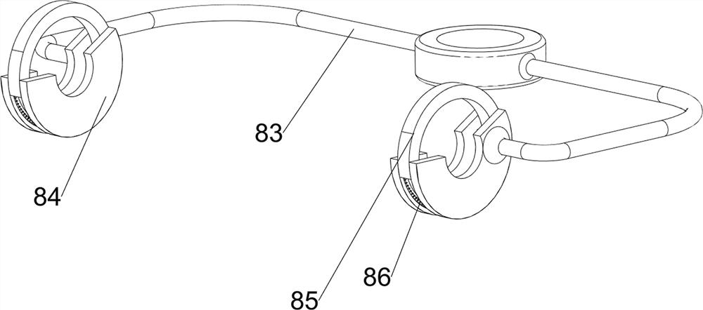
[0033] On the basis of Example 1, such as figure 1 , image 3 , Figure 4 and Figure 5 As shown, the collection mechanism 8 includes a collection frame 81, a collection pipe 82, a first support 83, a first slide rail 84, a movable plate 85 and a first spring 86, and a collection frame 81 is arranged in the placement frame 7, and the collection frame 81 The rear side is connected with a collection pipe 82, the upper side of the support rod 3 is provided with a first bracket 83, and the left and right sides of the first bracket 83 are provided with a first slide rail 84, and the first slide rail 84 is provided with a sliding plate 85 , a first spring 86 is connected between the movable plate 85 and the first slide rail 84 .
[0034] The user can collect the liquid during the operation through the collection tube 82, the liquid flows to the collection frame 81 through the collection tube 82, and then flows into the placement frame 7, so that the liquid can be collected, when ...
Embodiment 3
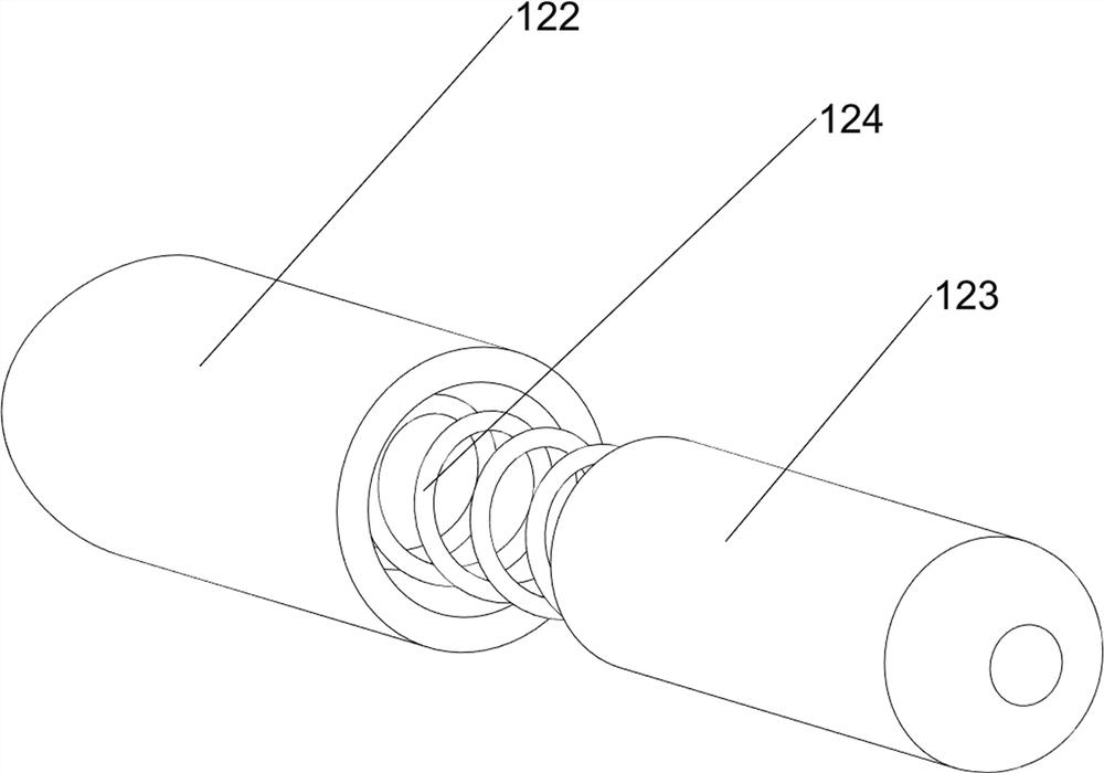
[0036] On the basis of Example 2, such as figure 1 , Figure 6 , Figure 7 , Figure 8 , Figure 9 and Figure 10 As shown, the disinfection mechanism 9 includes a first pressing plate 91, a second slide rail 92, a second spring 93, a third spring 94 and a flexible pipe 95, and the top of the disinfection frame 4 is slidably provided with a first pressing plate 91, and the disinfection frame 4 and the The second spring 93 is connected between the first pressing plate 91, and the left and right sides of the first pressing plate 91 are provided with the second slide rail 92, and the second slide rail 92 is slidably connected with the first fixed frame 6, and the second slide rail 92 is connected with the first fixed frame 6. A third spring 94 is connected between the first fixing frame 6 , and a hose 95 is connected between the left and right sides of the disinfection frame 4 and the collecting frame 81 .
[0037]When the user needs to sterilize the collection frame 81 and ...
PUM
 Abstract
Description
Claims
Application Information
 - R&D Engineer
- R&D Manager
- IP Professional
- Industry Leading Data Capabilities
- Powerful AI technology
- Patent DNA Extraction
Browse by: Latest US Patents, China's latest patents, Technical Efficacy Thesaurus, Application Domain, Technology Topic, Popular Technical Reports.
© 2024 PatSnap. All rights reserved.Legal|Privacy policy|Modern Slavery Act Transparency Statement|Sitemap|About US| Contact US: help@patsnap.com