
Medical disinfection device

A disinfection device and medical technology, applied in disinfection, water supply devices, applications, etc., can solve the problems of low flushing efficiency, incomplete flushing, etc., and achieve high efficiency

Pending Publication Date: 2022-04-22
墨轩(沭阳)高新科技有限公司
View PDF12 Cites 0 Cited by
  • Summary
  • Abstract
  • Description
  • Claims
  • Application Information

AI Technical Summary

Problems solved by technology

[0003] After the operation, a lot of blood stains are easily attached to the outer surfaces of some medical instruments such as scalpels and surgical scissors. In the existing medical disinfection devices, the medical staff generally wash the blood stains on the medical instruments one by one. Then put it into a disinfection cabinet for disinfection, but because of the large number of medical instruments, on the one hand, the efficiency of washing one by one is too low, and on the other hand, it may cause the situation that the washing is not careful and thorough, so we propose a medical disinfection device

Method used


Image

  • Medical disinfection device
  • Medical disinfection device
  • Medical disinfection device

Examples


Embodiment 1

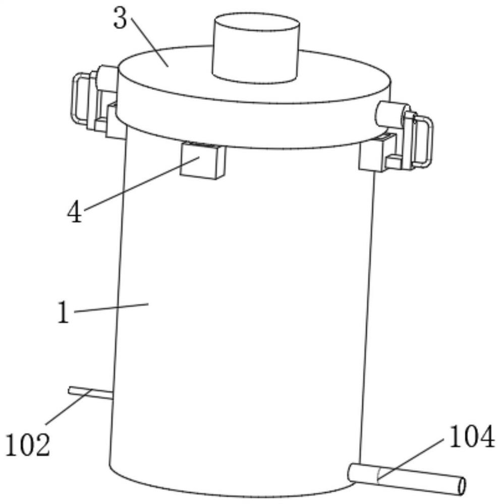
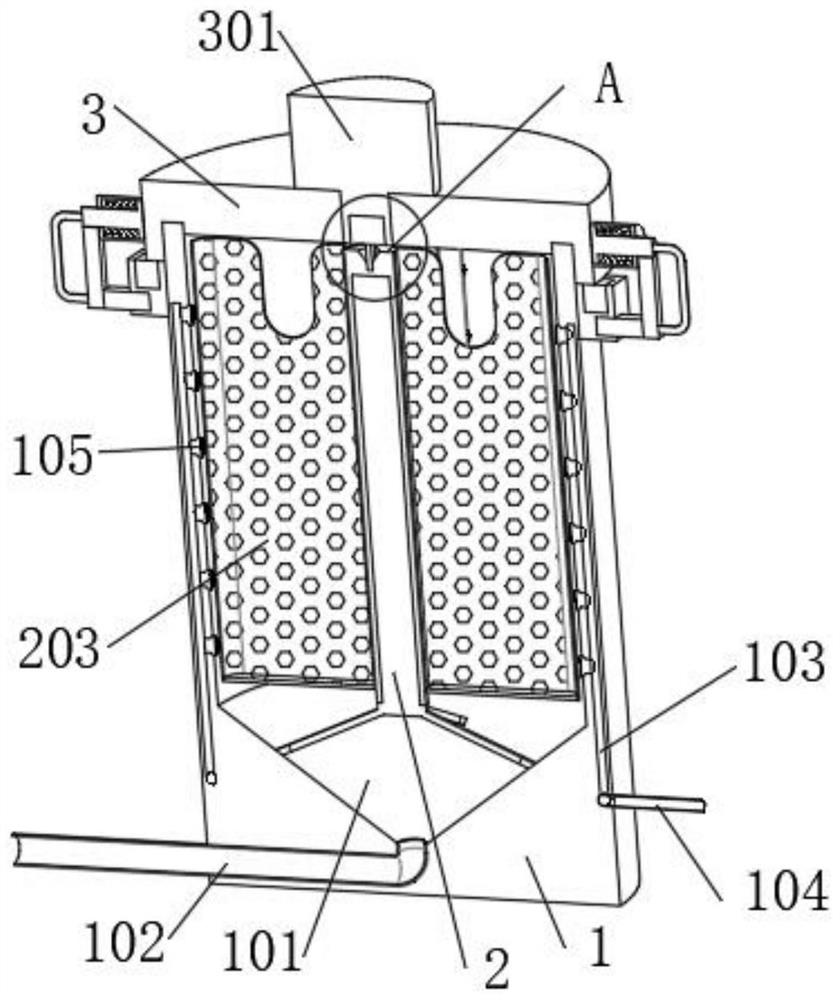
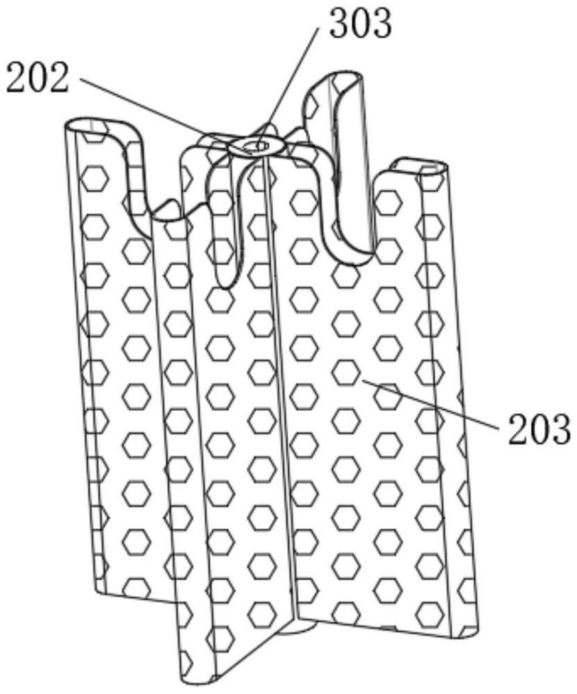
[0030] The embodiment of the invention discloses a medical disinfection device.

[0031] Please refer to the attached Figure 1-4 ,include:

[0032] Disinfection tank 1, the interior of disinfection tank 1 is provided with a cavity, and the inner bottom wall of the cavity is provided with a conical sump 101, and the opening of the bottom of the conical sump 101 is fixedly connected with a drain pipe 102, and the end of the drain pipe 102 part through the outer wall of the disinfection tank 1 and extends outwards. The inside of the disinfection tank 1 is equipped with a plurality of water distribution pipes 103, and the plurality of water distribution pipes 103 are connected to the water inlet pipe 104, and the end of the water inlet pipe 104 passes through the outer wall of the disinfection tank 1 Extending outward, the outer circular surface of the water distribution pipe 103 is equipped with a plurality of nozzles 105, and the plurality of nozzles 105 are embedded on the in...

Embodiment 2

[0043] The embodiment of the invention discloses a medical disinfection device.

[0044] Please refer to the attached Figure 1-4 ,include:

[0045] Disinfection tank 1, the interior of disinfection tank 1 is provided with a cavity, and the inner bottom wall of the cavity is provided with a conical sump 101, and the opening of the bottom of the conical sump 101 is fixedly connected with a drain pipe 102, and the end of the drain pipe 102 part through the outer wall of the disinfection tank 1 and extends outwards. The inside of the disinfection tank 1 is equipped with a plurality of water distribution pipes 103, and the plurality of water distribution pipes 103 are connected to the water inlet pipe 104, and the end of the water inlet pipe 104 passes through the outer wall of the disinfection tank 1 Extending outward, the outer circular surface of the water distribution pipe 103 is equipped with a plurality of nozzles 105, and the plurality of nozzles 105 are embedded on the in...


PUM


Abstract

The invention discloses a medical disinfection device, and relates to the field of medical equipment. The medical disinfection device comprises a disinfection tank, a plurality of water distribution pipes are assembled in the disinfection tank, the plurality of water distribution pipes are connected with a water inlet pipe, a plurality of nozzles are assembled on the outer circle surface of each water distribution pipe, and the plurality of nozzles are embedded in the inner wall of the disinfection tank; the outer surface of the supporting rod is movably sleeved with a sleeve, and the outer circle surface of the sleeve is fixedly connected with four placing filter frames; a clamping assembly is arranged between the sealing cover and the disinfection tank, a driving motor is fixedly mounted on the upper surface of the sealing cover, and a transmission assembly is arranged between the driving motor and the sleeve. According to the medical disinfection device, the four placing filter frames and a plurality of scalpels in the placing filter frames rotate, so that a plurality of nozzles wash the plurality of rotating scalpels, and an effective cleaning and disinfection effect is achieved.

Description

technical field [0001] The invention relates to the technical field of medical equipment, in particular to a medical disinfection device. Background technique [0002] At present, in medical work, the use of medical instruments for surgical treatment is one of the very common treatment methods. Non-disposable medical instruments need to be sterilized after use to avoid cross-infection when they are used again. [0003] After the operation, a lot of blood stains are easily attached to the outer surfaces of some medical instruments such as scalpels and surgical scissors. In the existing medical disinfection devices, the medical staff generally wash the blood stains on the medical instruments one by one. Then put it into a disinfection cabinet for disinfection, but because of the large number of medical instruments, on the one hand, the efficiency of washing one by one is too low, and on the other hand, it may cause the situation that the washing is not careful and thorough, so...

Claims


Application Information

Patent Timeline
Patent Type & Authority Applications(China)
IPC IPC(8): B08B3/02B08B13/00A61B90/70A61L2/18A61L2/26
CPCB08B3/022B08B13/00A61B90/70A61L2/18A61L2/26
Inventor 李华柱
Owner 墨轩(沭阳)高新科技有限公司
Learn More