Random array antenna pattern synthesis method considering mutual coupling effect

A technology of antenna pattern and random array, applied in special data processing applications, instruments, calculation models, etc., can solve the problems of easy local convergence of traditional particle swarm algorithm, and achieve the effect of overcoming local convergence, improving accuracy, and precise beam design

Pending Publication Date: 2022-04-22
NO 54 INST OF CHINA ELECTRONICS SCI & TECH GRP
View PDF0 Cites 0 Cited by
  • Summary
  • Abstract
  • Description
  • Claims
  • Application Information

AI Technical Summary

Problems solved by technology

[0007] (2) The traditional particle swarm opti

Method used


Image

  • Random array antenna pattern synthesis method considering mutual coupling effect
  • Random array antenna pattern synthesis method considering mutual coupling effect
  • Random array antenna pattern synthesis method considering mutual coupling effect

Examples


Embodiment 1

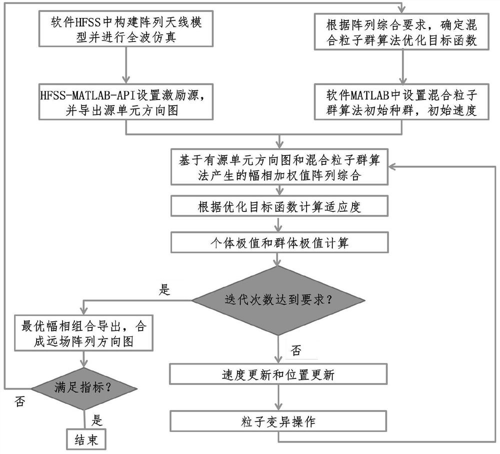
[0067] Embodiment 1: For a right-handed circularly polarized antenna, a 4×4 X-band right-handed circularly polarized microstrip antenna array is taken as an example to solve the beam synthesis problem of sidelobe suppression. In order to reduce the amount of calculation on the basis of ensuring the comprehensive performance of the array, and the weighted distribution of the amplitude and phase has been determined to be symmetrical about the center of the array based on prior knowledge, we can only consider with Array pattern in two directions. because The sidelobes of the array pattern in the direction are smaller than direction, so one can only consider Array pattern in one direction, the ultimate goal is to achieve sidelobe suppression of 20dB. Such as figure 1 As shown, the specific steps of the antenna pattern synthesis method are as follows:

[0068] Step 1: According to the system application index, determine the microstrip antenna whose center frequency is 8....

Embodiment 2

[0091] Embodiment 2: For a left-handed circularly polarized antenna, a 4×4 K-band left-handed circularly polarized microstrip antenna array is taken as an example to solve the radiation flat-top wide beam synthesis problem. In order to reduce the amount of calculation on the basis of ensuring the comprehensive performance of the array, and the weighted distribution of the amplitude and phase has been determined to be symmetrical about the center of the array based on prior knowledge, we can only consider with The array pattern in two directions satisfies the 3dB beamwidth up to 80°. Such as figure 1 As shown, the specific implementation steps of the antenna pattern synthesis method are as follows:

[0092] Step 1: According to the system application index, determine the microstrip antenna whose center frequency is 14.75GHz, the number of array elements is 4×4, and the array element spacing is 10.5mm. Use the full-wave electromagnetic simulation software HFSS to establish a...

Embodiment 3

[0099] Embodiment 3: For a large-scale linearly polarized array, a 16×16 Ka-band linearly polarized microstrip antenna array is taken as an example to solve the radiation flat-top wide beam synthesis problem. only consider with Array patterns in two directions, the ultimate goal is to achieve a 3dB beamwidth of 50° and a sidelobe level of less than -10dB. Such as figure 1 As shown, the specific implementation steps of the antenna pattern synthesis method are as follows:

[0100] Step 1: According to the system application index, determine the microstrip antenna whose center frequency is 30GHz, the number of array elements is 16×16, and the array element spacing is 5mm. Use the full-wave electromagnetic simulation software HFSS to establish a two-dimensional rectangular array antenna model. Perform full-wave electromagnetic simulations such as Figure 8 shown. For large-scale arrays, quickly extract all active element patterns through HFSS-MATLAB-API;

[0101] Step 2: D...


PUM


Abstract

The invention discloses a random array antenna pattern synthesis method considering a mutual coupling effect, and belongs to the technical field of antenna array pattern synthesis. The method comprises an antenna array modeling step, an antenna array directional diagram generation step and an optimal amplitude-phase weighted acquisition step. According to the method, the mutual coupling effect between array antenna units and the polarization characteristic of the array antenna are considered, an accurate antenna array model is constructed in combination with an active unit directional diagram, and the antenna array directional diagram is rapidly optimized by using a hybrid particle swarm optimization algorithm for a target array directional diagram, so that the optimization efficiency is improved. And finally, beamforming such as beam broadening, low sidelobe and phased array scanning is realized.

Description

technical field [0001] The invention belongs to the technical field of antenna array pattern synthesis, and in particular relates to a random array antenna pattern synthesis method considering mutual coupling effect. [0002] technical background [0003] Array antennas are widely used in radar, communication, navigation and positioning and other fields because they can perform beamforming according to different application scenarios to improve system performance. In order to obtain a pattern that meets specific requirements, many array synthesis algorithms are used to solve the excitation amplitude and phase values ​​of the array antenna radiating elements, mainly including analytical methods, numerical methods, and stochastic optimization algorithms. Compared with the traditional array synthesis algorithm, the stochastic optimization algorithm has the advantages of global search, dynamic adjustment of the objective function, and simultaneous optimization of multiple objecti...

Claims


Application Information

Patent Timeline
IPC IPC(8): G06F30/20G06N3/00
CPCG06F30/20G06N3/006
Inventor 赵琪魏浩韩威魏恒王亚舟周媛卢云龙赵建欣刘子奕
Owner NO 54 INST OF CHINA ELECTRONICS SCI & TECH GRP
Why Eureka
Try Eureka