Magnetic disk inspection method for magnetic disk device, and magnetic disk device

A technology of a magnetic disk device and an inspection method, which is applied in the field of disk inspection of a magnetic disk device and the field of a magnetic disk device, and can solve problems such as poor recording signal quality, difficulty in reading recorded information, and reduced recording quality

Pending Publication Date: 2022-04-22
KK TOSHIBA +1
View PDF0 Cites 0 Cited by
  • Summary
  • Abstract
  • Description
  • Claims
  • Application Information

AI Technical Summary

Problems solved by technology

The quality of the recording signal at such a defective part is poor. Even if there is no abnormality during the factory inspection, the recording quality of this part will decrease due to repeated recording on adjacent tracks, and it will become difficult to read the recorded information.
In addition, the presence of protrusions on the magnetic disk may damage the recording head, resulting in damage to the reliability of the magnetic disk device.

Method used


Image

  • Magnetic disk inspection method for magnetic disk device, and magnetic disk device
  • Magnetic disk inspection method for magnetic disk device, and magnetic disk device
  • Magnetic disk inspection method for magnetic disk device, and magnetic disk device

Examples


no. 1 Embodiment approach

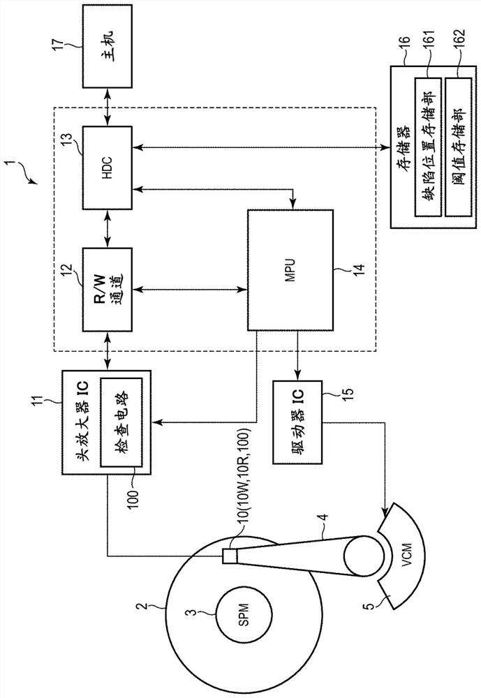
[0029] figure 1 It is a block diagram showing an example of the configuration of the magnetic disk drive 1 according to the first embodiment.

[0030] Such as figure 1 As shown, the magnetic disk device 1 is configured as, for example, a hard disk drive (HDD). The magnetic disk device 1 includes a magnetic disk 2, a spindle motor (SPM) 3, an actuator 4, a voice coil motor (VCM) 5, a magnetic head 10, a head amplifier IC (preamplifier) ​​11, an R / W channel 12, and a hard disk controller ( HDC) 13 , microprocessor (MPU) 14 , driver IC 15 , and memory 16 .

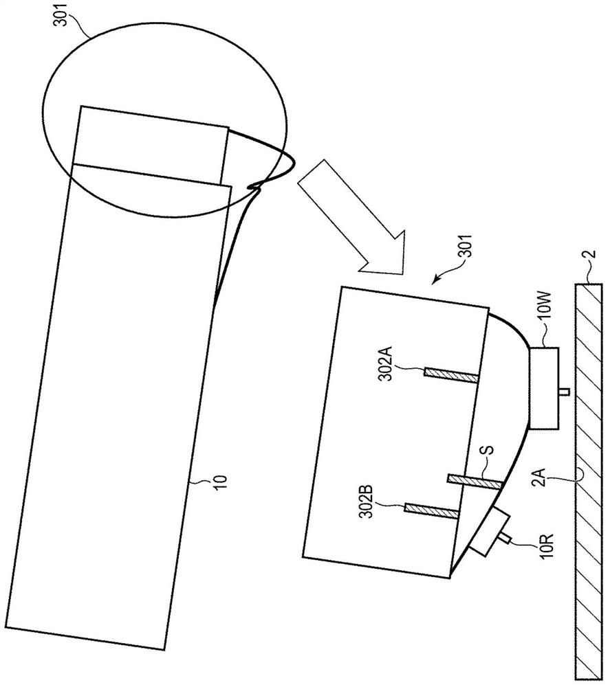
[0031] In addition, the magnetic disk device 1 can be connected to the host computer 17 . Although the details will be described later, the magnetic head 10 includes a write head 10W, a read head 10R, and a spin-torque oscillator (Spin-Torque-Oscillator: STO) 100 as a high-frequency oscillation element. In addition, the R / W channel 12, the HDC 13 and the MPU 14 can also be assembled in an integrated circuit of a single ch...

no. 2 Embodiment approach

[0094] The second embodiment is different from the first embodiment in that a defect of the magnetic disk 2 is detected not in units of tracks but in units of sectors. Therefore, the configuration and processing for detecting defects on a sector-by-sector basis will be described in detail. In addition, the same code|symbol is attached|subjected to the same structure as 1st Embodiment, and detailed description about these structures is abbreviate|omitted.

[0095] When the defect of the magnetic disk 2 is a defect such as a groove constituted by the concave portion 2C along the circumferential direction of the track, the length of the groove may be limited. For example, when a track is composed of a plurality of sectors, a case where a defect is accommodated in one sector is also considered. In this case, it is assumed that when the LPF outputs in one track are averaged, the output level becomes small, so that the detection sensitivity deteriorates, and the presence of a defec...


PUM


Abstract

Embodiments provide a magnetic disk inspection method for a magnetic disk device and a magnetic disk device capable of accurately detecting defects on a magnetic disk. A magnetic disk device according to an embodiment includes a preamplifier including a first processing unit including a first filter that filters an output of a gap sensor at a predetermined frequency, and a second processing unit including a second filter that filters the output of the gap sensor at the predetermined frequency. And a second processing unit having a second filter for filtering the output of the gap sensor at a frequency higher than the frequency of the first filter. The magnetic disk device uses a first processing unit and a second processing unit to inspect a defect on a recording surface of a magnetic disk on the basis of an output of a gap sensor. And a detection unit that compares a threshold value defined on the basis of the output of the first processing unit that excludes the plurality of tracks following the track to be inspected with the output of the first processing unit that is the track to be inspected, and detects that there is a defect in the track of the magnetic disk when the output of the first processing unit that is the track to be inspected exceeds the threshold value.

Description

[0001] This application enjoys the priority of the basic application based on Japanese Patent Application No. 2020-176105 (filing date: October 20, 2020). This application incorporates the entire content of the basic application by referring to this basic application. technical field [0002] Embodiments relate to a magnetic disk inspection method of a magnetic disk device and the magnetic disk device. Background technique [0003] A technique is known in which, in a magnetic disk drive, a damage on a recording medium is detected and the detected damage is registered. [0004] Minute magnetic defects, geometrical defects, such as protrusions, pits, or minute damages exist on the magnetic disc of the magnetic disc device. The quality of the recording signal at such a defective portion is poor, and even if there is no abnormality during the factory inspection, the recording quality of the portion will deteriorate due to repeated recording on adjacent tracks, making it difficu...

Claims


Application Information

Patent Timeline
Patent Type & Authority Applications(China)
IPC IPC(8): G11C29/56
CPCG11C29/56008G11C2029/5606G11B19/048G11B2220/2516G11B5/6076G11B5/455
Inventor 渡边彻
Owner KK TOSHIBA
Why Eureka
Try Eureka