Tunnel pipe distribution vehicle with protection function

A protective function and the technology of pipe-laying vehicles, which are applied in the direction of freight vehicles, vehicles used to carry long goods, motor vehicles, etc., can solve the problems that the side of the pipe cannot be blocked and protected, and can avoid the pipe from falling Effect

Pending Publication Date: 2022-04-29
席秀杰
View PDF1 Cites 2 Cited by
  • Summary
  • Abstract
  • Description
  • Claims
  • Application Information

AI Technical Summary

Problems solved by technology

[0005] In order to overcome the shortcomings of the existing pipeline construction automatic transporting and distributing vehicles that cannot shield and protect the side of the pipeline, the technical problem to be solved is to provide a tunnel pipe layout with a protective function that can limit and protect the side of the pipeline. car

Method used


Image

  • Tunnel pipe distribution vehicle with protection function
  • Tunnel pipe distribution vehicle with protection function
  • Tunnel pipe distribution vehicle with protection function

Examples


Embodiment 1

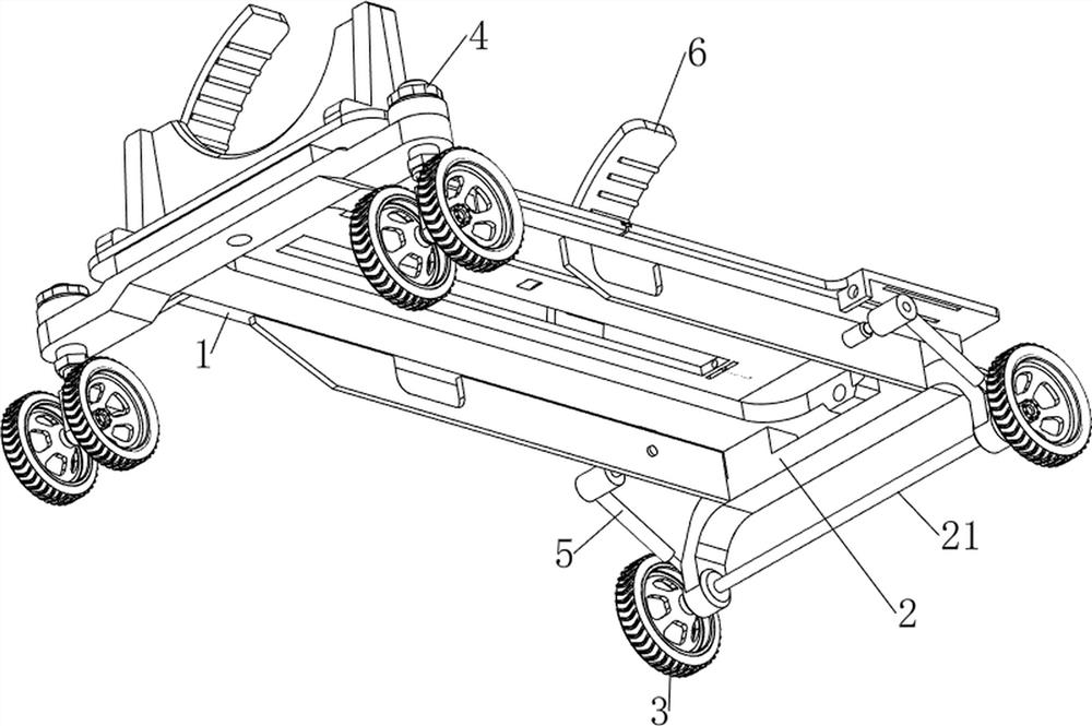
[0032] A tunnel pipe laying vehicle with protection function, such as Figure 1-3 As shown, it includes a bearing plate 1, a support frame 2, a connecting shaft 21, a wheel 3, a load-bearing rod 4, a support rod 5, a first protective plate 6, a closing mechanism 7 and a limit mechanism 8, and the bottom of the bearing plate 1 is provided with a support Frame 2, the support frame 2 can support the bearing plate 1, the lower part of the right side of the support frame 2 is rotatably connected with a connecting shaft 21, and the front and rear sides of the connecting shaft 21 are connected with wheels 3, the wheels 3 can roll on the ground, and the support frame 2 The front and rear sides of the left part are all rotatably connected with a load-bearing bar 4, and the load-bearing bar 4 is also rotatably connected with a wheel 3. The first protective plate 6, the first protective plate 6 can be used to protect the pipeline, the support frame 2 is connected with a closing mechanism...

Embodiment 2

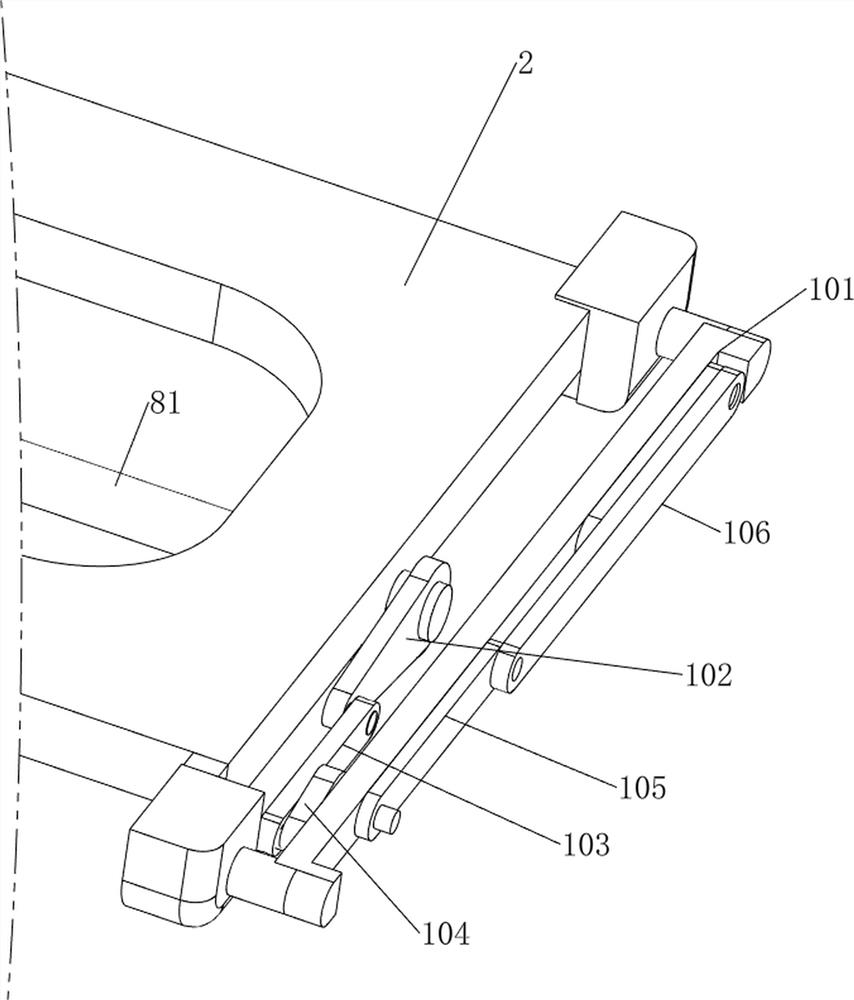
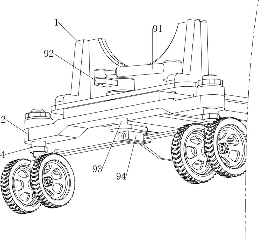
[0037] On the basis of Example 1, such as figure 1 , figure 2 , Figure 7 and Figure 8 As shown, an adjustment mechanism 9 is also included, which can adjust the steering of the left wheel 3, and then adjust the moving direction. The adjustment mechanism 9 includes a cylinder 91, a first rotating rod 92, a second rotating rod 93 and a second connecting rod 94 The left front side of the bearing plate 1 is connected with a cylinder 91 by screws, the second rotating rod 93 is rotationally connected between the bearing plate 1 and the left middle part of the support frame 2, and the first rotating rod 92 is welded on the left side of the upper part of the second rotating rod 93 , the first rotating rod 92 and the telescopic rod of the cylinder 91 are connected in a rotational manner, and the telescopic rod of the cylinder 91 can drive the first rotating rod 92 to rotate. A second connecting rod 94 is connected, and the second connecting rod 94 is slidingly connected to the bo...


PUM


Abstract

The invention relates to a tunnel pipe distribution vehicle, in particular to a tunnel pipe distribution vehicle with a protection function. The technical problem to be solved is to provide the tunnel pipe distribution vehicle with the protection function, which can limit and protect the side edge of a pipeline. According to the technical scheme, the tunnel pipe distribution vehicle with the protection function comprises a bearing plate, a supporting frame, a connecting shaft, wheels, a bearing rod, a supporting rod and the like, the supporting frame is arranged at the bottom of the bearing plate, the connecting shaft is rotationally arranged on the lower portion of the right side of the supporting frame, and the wheels are arranged on the front side and the rear side of the connecting shaft; bearing rods are rotationally arranged on the front side and the rear side of the left portion of the supporting frame, and wheels are rotationally arranged on the bearing rods. The first motor is controlled to work, the rotating plate can swing upwards, then under the action of the first protection plate, the pipeline can be clamped and limited, and in this way, in the transportation process, the pipeline can be prevented from falling off.

Description

technical field [0001] The invention relates to a tunnel pipe laying vehicle, in particular to a tunnel pipe laying vehicle with protection function. Background technique [0002] During the pipeline construction process of the tunnel, the pipeline needs to be transported to the construction site in a unified manner, and then the workers will lay the pipeline. The current transportation method usually uses vehicles, but the transportation cost of vehicles is relatively high, and it is not suitable for short-distance transportation. [0003] The patent application number is CN201420099887.X, an automatic pipe transportation vehicle for pipeline construction, which includes a vehicle chassis that is supported on wheels and can be driven and walked. The driver's seat is located on the left side of the front part of the vehicle chassis. A front bracket is vertically connected, and a rear bracket is vertically connected above the rear of the vehicle chassis. The front bracket and...

Claims


Application Information

Patent Timeline
Patent Type & Authority Applications(China)
IPC IPC(8): B60P7/12B60P3/40
CPCB60P7/12B60P3/40
Inventor 席秀杰
Owner 席秀杰
Why Eureka
Try Eureka