Pressurizing device and rotary drilling rig
A technology of pressurizing device and rotary drilling rig, which is applied in the directions of drilling pipe, drill pipe, earthwork drilling, etc. Operation, low cost, effect of preventing interference
- Summary
- Abstract
- Description
- Claims
- Application Information
AI Technical Summary
Problems solved by technology
Method used
Image

Examples
Embodiment 1
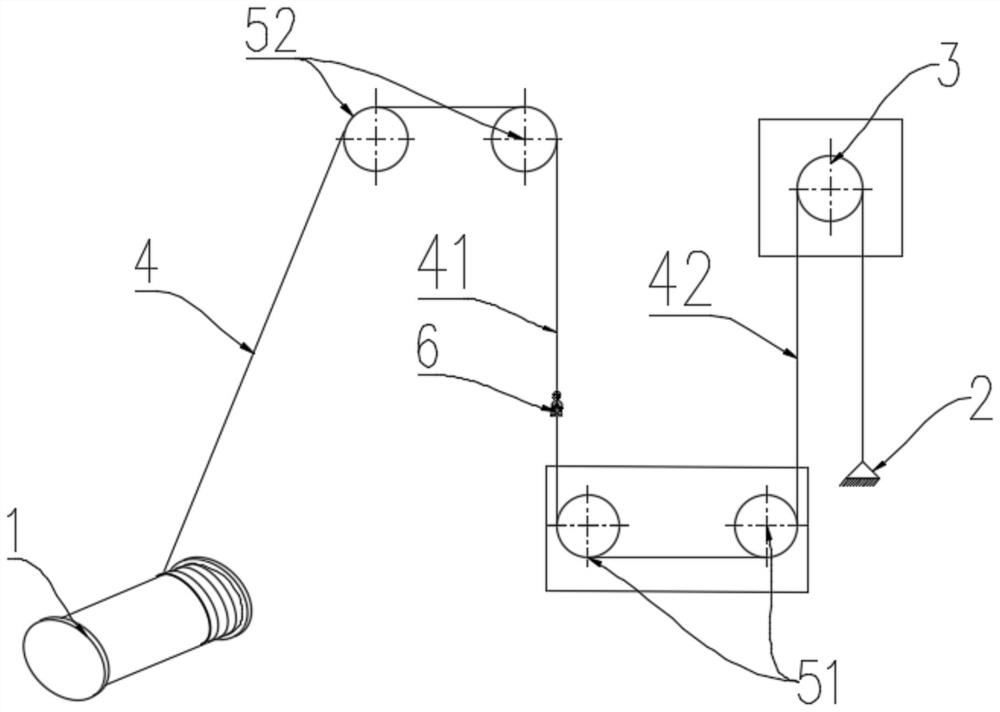
[0036]A pressing device includes a winding mechanism 1 , a fixing seat 2 , a pressing pulley 3 , a reversing pulley block 5 and a locking assembly 6 . Wherein, the pressure pulley 3 is arranged between the winding mechanism 1 and the connecting circuit of the fixed seat 2, and the pressure pulley 3 is wound with a steel wire rope 4, and one end of the steel rope 4 is connected with the winding mechanism 1, and the other end of the steel rope 4 is connected with the fixed The seat 2 is connected; the steel wire rope 4 between the connection circuit between the pressure pulley 3 and the winding mechanism 1 and / or the connection circuit between the pressure pulley 3 and the fixed seat 2 is connected by a reversing pulley block 5; the steel wire rope 4 includes the first steel wire rope 41 and the second wire rope 42, the first wire rope 41 is connected with the second wire rope 42 through the lock assembly 6, and is suitable for pressurizing the press pulley 3; the first wire rope...
Embodiment 2
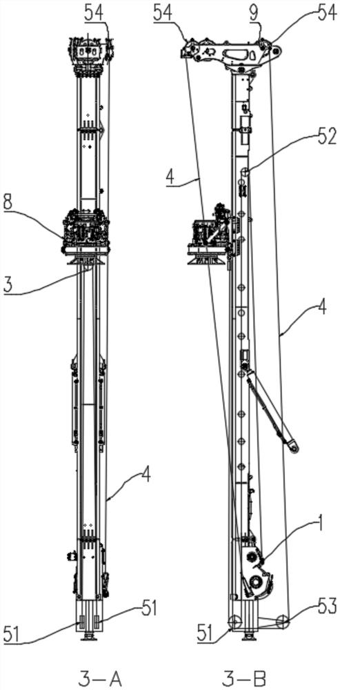
[0049] The difference between this embodiment and Embodiment 1 is that the reversing pulley also includes a second reversing pulley set arranged between the pressure pulley 3 and the fixed seat 2; The third fixed pulley 53 and the fourth fixed pulley 54 located in the space above the third fixed pulley 53, similarly, as mentioned above, in the vertical direction, the third fixed pulley 53 is located in the space below the pressure pulley 3, and in the horizontal direction There is no restriction in the direction; in the vertical direction, the fourth fixed pulley 54 is located in the space above the third fixed pulley 53, and there is no restriction in the horizontal direction. One end of the wire rope 4 on the pressure pulley 3 is connected with the fixed seat 2 after going around the third fixed pulley 53 and the fourth fixed pulley 54 in turn.
[0050] refer to image 3 with Figure 4 , image 3 -A is a schematic structural view of the pressurizing device arranged on the...
Embodiment 3
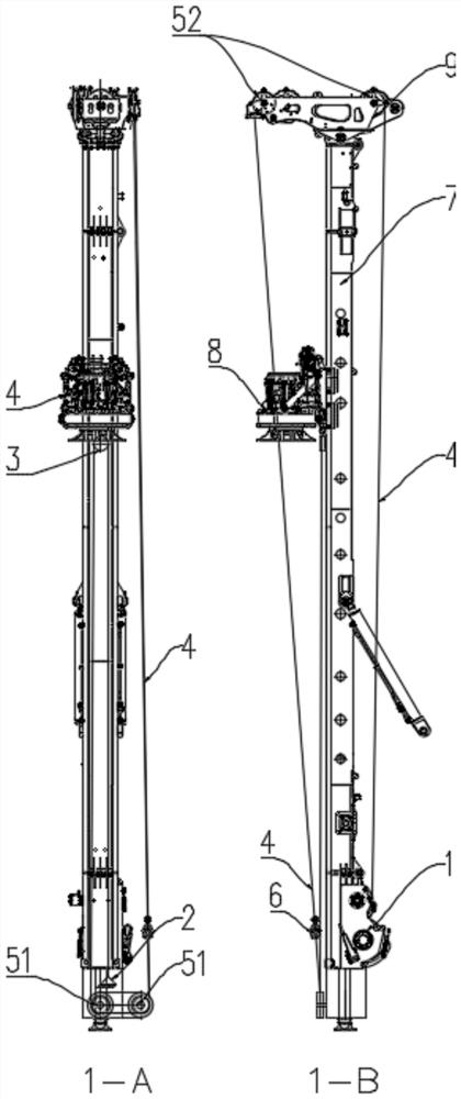
[0055] A rotary drilling rig, including the pressurizing device described in Embodiment 1 or Embodiment 2, wherein the winding mechanism 1 includes a reel of the auxiliary hoisting mechanism of the rotary drilling rig and a drive motor connected to the reel; 2 is fixedly arranged on the lower part of the mast 7 of the rotary drilling rig; the pressure pulley 3 is fixedly arranged on the power head 8 of the rotary drilling rig.
[0056] When the rotary drilling rig performs CFA construction, the first steel wire rope 41 and the second steel wire rope 42 are connected through the first buckle 61 and the second buckle 62, and the reel winds the steel wire rope 4 to pressurize the pulley 3, that is, to Power head 8 exerts drilling pressure.
[0057] When the rotary drilling rig is switched to other construction methods, such as the need to lift the reinforcement cage. Now, the first buckle 61 and the second buckle 62 are untied, and the end of the first steel wire rope 41 is conn...
PUM
 Abstract
Description
Claims
Application Information
 - R&D Engineer
- R&D Manager
- IP Professional
- Industry Leading Data Capabilities
- Powerful AI technology
- Patent DNA Extraction
Browse by: Latest US Patents, China's latest patents, Technical Efficacy Thesaurus, Application Domain, Technology Topic.
© 2024 PatSnap. All rights reserved.Legal|Privacy policy|Modern Slavery Act Transparency Statement|Sitemap