Under-screen monitoring display device

A display device, a technology for normal display, applied in the directions of instruments, TVs, color TV components, etc., can solve the problems of large chromatic aberration in the display area, high RGB photoresist transmittance, poor integrated black effect, etc., to improve reflection. The effect of the same rate and reflectivity

Pending Publication Date: 2022-04-29
WUHAN CHINA STAR OPTOELECTRONICS TECH CO LTD
View PDF16 Cites 0 Cited by
  • Summary
  • Abstract
  • Description
  • Claims
  • Application Information

AI Technical Summary

Problems solved by technology

[0005] Based on the existing technical problems, this application provides an under-screen monitoring and display device, which can solve the problem that the DMS module used in the existing under-screen liquid crystal display device has an infrared sensing module, and the infrared sensing module collects optical signals in the 650nm-940nm band , RGB photoresist has a high transmittance in the IR band, and can image images through the light-shielding layer on the surface of the glass cover. Since the existing imaging area is a through hole, the corresponding imaging area on the color filter side of the LCD panel is generally designed not to use BM / RGB / PS photoresist, so the color difference between the camera area and the normal display area is relatively large, the DMS module cannot be hidden under the display panel, and there is a technical problem that the overall black effect is not good when the display device is turned off

Method used


Image

  • Under-screen monitoring display device
  • Under-screen monitoring display device
  • Under-screen monitoring display device

Examples


Embodiment Construction

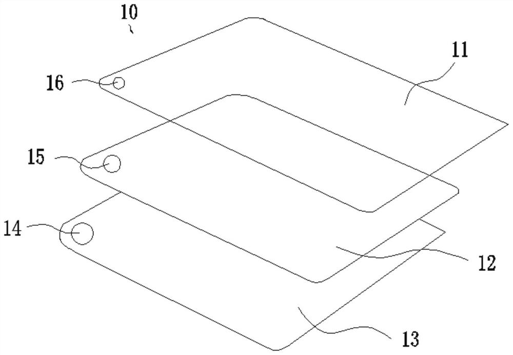
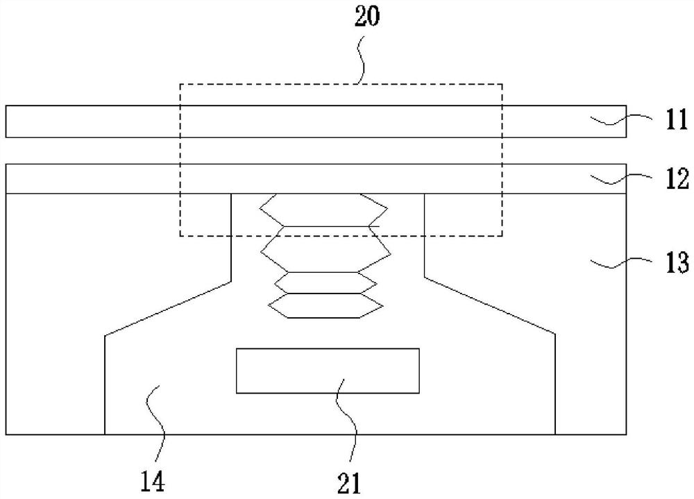
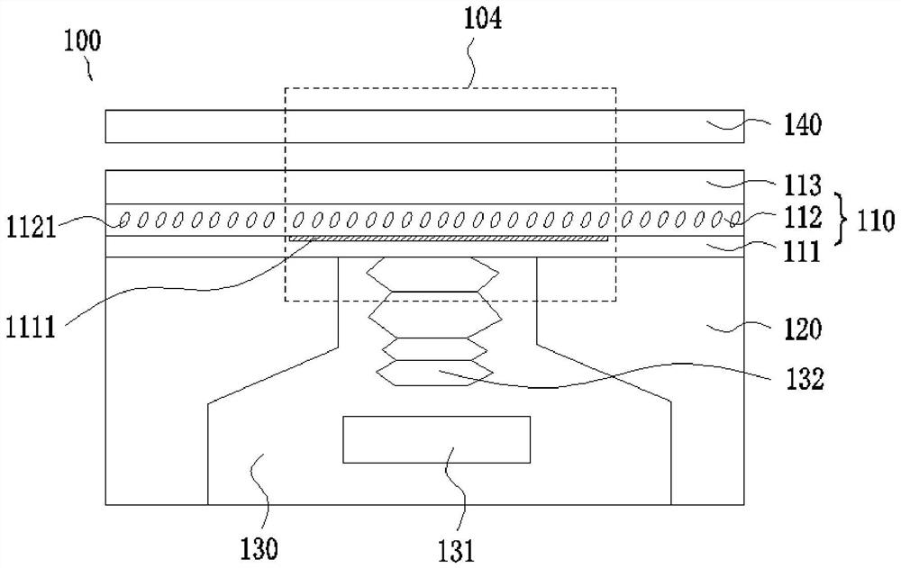
[0026] The following descriptions of the various embodiments refer to the accompanying drawings to illustrate specific embodiments in which the invention may be practiced. The directional terms mentioned in the present invention, such as [top], [bottom], [front], [back], [left], [right], [inside], [outside], [side], etc., are only for reference The orientation of the attached schema. Therefore, the directional terms used are used to illustrate and understand the present invention, but not to limit the present invention. In the figure, units with similar structures are indicated by the same reference numerals, and the dotted lines in the figure indicate that they do not exist in the structure, and only illustrate the shape and position of the structure.

[0027] According to the present invention, the DMS module used in the existing under-screen liquid crystal display device has an infrared sensing module. The infrared sensing module collects optical signals in the 650nm-940nm...


PUM


Abstract

The invention provides an under-screen monitoring display device. The under-screen monitoring display device comprises a liquid crystal panel and a backlight module located on the back of the liquid crystal panel. The display panel comprises at least one camera shooting area used for receiving external light, and the backlight module is provided with a backlight hole corresponding to the camera shooting area; a monitoring system is arranged in the backlight hole, the monitoring system comprises a DMS module with an infrared sensor, and an infrared ray penetrating layer is arranged on the daylighting path of the DMS module; the side, away from the backlight module, of the liquid crystal panel is further provided with a protective cover plate, and the color of the infrared transmitting layer is consistent with the surface color of the protective cover plate, so that the reflectivity of a camera shooting area is properly improved, the reflectivity of the camera shooting area is consistent with that of a normal display area, and a better integrated black effect during shutdown is achieved.

Description

technical field [0001] The invention relates to the field of display technology, in particular to an under-screen monitoring and display device. Background technique [0002] DMS, the full name of Driver Monitor System, is the driver status monitoring system. The early DMS was mainly driver fatigue monitoring. With the gradual maturity of automatic driving, Internet of Vehicles and related technologies, more functions have been gradually evolved and iterated. The DMS monitoring system mainly includes basic functions such as smoking monitoring, phone call monitoring, distracted driving monitoring, seat belt not wearing monitoring, drinking water monitoring, yawning monitoring, eye closure monitoring, and abnormal state monitoring. [0003] Use the images acquired by the DMS module to detect the driver's driving behavior and physiological state through visual tracking, target detection, action recognition and other technologies. In the event of a situation, the system will g...

Claims


Application Information

Patent Timeline
Patent Type & Authority Applications(China)
IPC IPC(8): G02F1/1333G02F1/1335G02F1/1343G02F1/1339G02F1/1362H04N5/225
CPCG02F1/1333G02F1/133331G02F1/133512G02F1/133514G02F1/1343G02F1/13394G02F1/1362H04N23/57
Inventor 贺强张如庆刁庚秀
Owner WUHAN CHINA STAR OPTOELECTRONICS TECH CO LTD
Why Eureka
Try Eureka