
A low-level lighting fixture for a tunnel

A technology for lighting lamps and tunnels, which is applied to outdoor lighting, lighting devices, fixed lighting devices, etc., can solve the problems of unreachable reflectors, difficult maintenance and maintenance, and low lighting efficiency, so as to reduce maintenance costs and improve light energy. Utilization rate, the effect of solving the glare problem

Inactive Publication Date: 2017-09-19
SHANDONG JIAOTONG UNIV +4
View PDF5 Cites 0 Cited by
  • Summary
  • Abstract
  • Description
  • Claims
  • Application Information

AI Technical Summary

Problems solved by technology

On the one hand, the existing tunnel lighting fixtures have low lighting efficiency, high energy consumption, and difficult repair and maintenance; on the other hand, due to the high installation position, such lamps are likely to cause glare to drivers and affect the driving safety of tunnel vehicles
[0003] There is a low pole lighting reflector light distribution device in the existing market, the lamp body is connected with the fixed bracket through the connecting bracket, the power box is installed at the rear, and the tempered glass panel is at the front; the end cover of the lamp is installed in the lamp body, and the lamp body The upper part of the LED light source is installed on the aluminum substrate. The light from the LED light source is directed to the reflector inside the lamp body, and reflected to the tempered glass panel through the reflector cup. A waterproof sealing strip is fixed between the tempered glass panel and the end cover of the lamp. , the reflective cup is composed of multiple curved surfaces, and the direction, shape and radian of the curved surfaces are different, but the patent has the following defects: After actual testing, the light distribution effect of the reflective cup has not reached the light distribution described in the patent. The effect of uniform reflection to the road surface, but the place farther away from the lamp has less light energy, and the place closer to the lamp has more light energy

Method used


Image

  • A low-level lighting fixture for a tunnel
  • A low-level lighting fixture for a tunnel

Examples


Embodiment 1

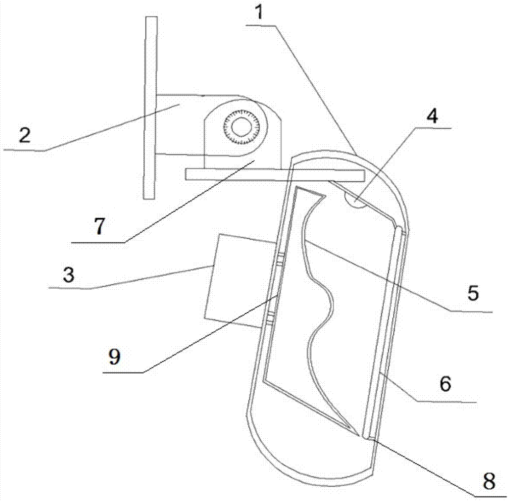
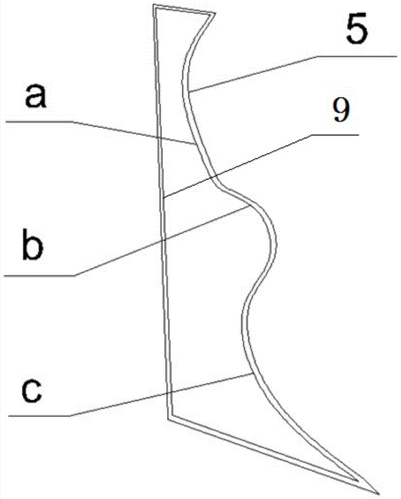
[0029] A tunnel low-level lighting fixture, which is installed on the tunnel wall at a distance of (1.0-1.5) m from the ground, including a lamp body 1, an angle-adjustable fixing bracket, a power supply box 3, a light source 4, a reflector cup 5, Glass panel 6, the lamp body 1 is arranged on the tunnel wall through the adjustable angle fixing bracket, the power supply box 3 is arranged at the rear of the lamp body 1, and the reflector 5 is arranged on the lamp body 1, the light source 4 is arranged on the upper part of the lamp body 1, the glass panel 6 is arranged on the front part of the lamp body 1, the light generated by the light source 4 is directed to the reflector cup 5, And reflected on the glass panel 6 through the reflective cup 5, the reflective cup 4 includes 2 parabolic arc surfaces and 1 free arc surface b, the free arc surface b is connected between the 2 parabolic arc surfaces, The shapes of the two parabolic arc surfaces are different, and the lengths of the...

Embodiment 2

[0033] According to the tunnel low-level lighting fixture described in Embodiment 1, the difference is that the angle between the light source 4 and the back plate 9 of the reflector 5 is 64°.

Embodiment 3

[0035] According to the tunnel low-level lighting fixture described in Embodiment 1, the difference is that the included angle between the light source and the back plate 9 of the reflector 5 is 66°.


PUM


Abstract

The invention relates to a low-position illumination lamp for a tunnel. The low-position illumination lamp is installed at the position, which is 1.0 mm to 1.5 mm away from the ground, of a wall of the tunnel; a reflection cup comprises two parabola arc faces and one free arc face, the free arc face is connected between the two parabola arc faces, the two parabola arc faces are different in shape, and the lengths of the two parabola arc faces are both larger than the length of the free arc face; the length of the parabola arc face close to the lower portion of a lamp body is larger than the length of the parabola arc face close to the upper portion of the lamp body; and an included angle between a lamp source and a flat plate on the back of the reflection cup ranges from 64 degrees to 66 degrees. After light is emitted by the lamp source is reflected by the reflection cup, a lighter light band and darker light bands are formed, the darker light bands generated by illumination lamps on the walls on the two sides of the tunnel are overlapped together, the luminance of the overlapped darker light bands is basically the same as the luminance of the lighter light band, low-position even illumination on the road surface of the tunnel is achieved, and the national standard requirement is met. Meanwhile, the illumination energy consumption is obviously reduced, and the problem of glaring is solved.

Description

technical field [0001] The invention relates to a tunnel low-level lighting fixture, which belongs to the technical field of lighting devices. Background technique [0002] At present, most of the lighting fixtures used in tunnels are ceiling lamps and pendant lights, and the installation positions are relatively high. No low-level lighting fixtures have been used in tunnels yet. On the one hand, the existing tunnel lighting lamps have low lighting efficiency, high energy consumption, and difficult repair and maintenance; on the other hand, due to the high installation position, such lamps are likely to cause glare to drivers and affect the safety of tunnel vehicles. [0003] There is a low pole lighting reflector light distribution device in the existing market, the lamp body is connected with the fixed bracket through the connecting bracket, the power box is installed at the rear, and the tempered glass panel is at the front; the end cover of the lamp is installed in the l...

Claims


Application Information

Patent Timeline
Patent Type & Authority Patents(China)
IPC IPC(8): F21S8/00F21V7/09F21V14/02F21V29/89F21V31/00F21W131/101F21Y115/10
CPCF21S8/036F21V7/09F21V14/02F21V31/005F21W2131/101
Inventor 邵新鹏高尚艾贻忠蔡建军孔存芝杨志强盖国晖郭保林
Owner SHANDONG JIAOTONG UNIV
Learn More