Laser inertial confinement fusion hot spot high spatial resolution detection system and method

An inertial confinement fusion, high spatial resolution technology, applied in the field of laser inertial confinement fusion hot spot high spatial resolution detection systems, can solve the problems of limited spatial resolution of multi-pinhole imaging, low accuracy of temperature density results, insufficient spatial resolution, etc. , to achieve the effect of reliable results, consistent reflectivity, and broad application prospects

Active Publication Date: 2020-11-24
LASER FUSION RES CENT CHINA ACAD OF ENG PHYSICS
View PDF9 Cites 0 Cited by
  • Summary
  • Abstract
  • Description
  • Claims
  • Application Information

AI Technical Summary

Problems solved by technology

[0004] The above detection methods often have the following deficiencies. First, the spatial resolution of multi-pinhole imaging is limited by the size of the pinhole. The pinhole is usually 10-25 μm, but the size of the hot spot is 30-60 μm. Collecting 3 to 6 data points, obviously the spatial resolution is insufficient; second, when doping elements, they are usually medium and high Z elements, these elements will bring radiation cooling effect, will reduce the temperature of the hot spot, and affect the measurement results ;Third, using the iterative calculation method, the accuracy of the obtained temperature and density results is relatively low

Method used


Image

  • Laser inertial confinement fusion hot spot high spatial resolution detection system and method
  • Laser inertial confinement fusion hot spot high spatial resolution detection system and method
  • Laser inertial confinement fusion hot spot high spatial resolution detection system and method

Examples


Embodiment Construction

[0036] The present invention will be further described below in conjunction with embodiment and accompanying drawing.

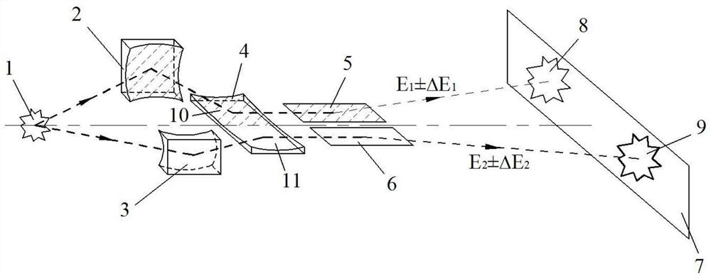
[0037] refer to figure 1 The laser inertial confinement fusion hot spot high-spatial-resolution detection system shown includes a flat-response spherical objective lens Ⅰ2 and a flat-response spherical objective lens II3 that are vertically arranged with the reflective surface facing upwards, and a composite flat-response objective lens that is horizontally arranged and the reflective surface is vertically upward Spherical objective lens Ⅲ4, set horizontally with the reflective surface vertically upward, flat response energy-selective plane mirror Ⅰ5, and flat-response energy selective plane mirror Ⅱ6, imaging plate 7 and laser phosphor screen analyzer 12;

[0038]Among them, the compound flat-response spherical objective lens III4 has symmetrically arranged flat-response reflective surfaces I10 and flat-response reflective surfaces II11, and both flat-respon...


PUM


Abstract

The invention discloses a laser inertial confinement fusion hot spot high spatial resolution detection system and method. The system comprises a flat response spherical objective lens I and a flat response spherical objective lens II which are vertically arranged and have reflecting surfaces opposite to each other, a composite flat response spherical objective lens III which is horizontally arranged and has a vertically upward reflecting surface, a flat response energy selection plane mirror I and a flat response energy selection plane mirror II which are horizontally arranged and have a vertically upward reflecting surface, an imaging plate and a laser phosphorus screen analyzer. The calculation method is mainly used for reading data and directly obtaining the electron temperature and density through the intensity ratio of the single-energy image according to the bremsstrahlung principle. Influence of view field difference is eliminated mainly through a double-KB-mirror channel system, and the reflectivity is ensured to be consistent by utilizing the flat response of the channel and the plane mirror, the absolute values of the electron temperature and density are calculated according to the bremsstrahlung radiation principle, the calculation process is simpler, the result is more reliable, the absolute hot spot electron density value can be solved, and the system and the method have wide and important application prospects.

Description

technical field [0001] The invention relates to the technical field of electronic parameter detection, in particular to a laser inertial confinement fusion hot spot detection system and method with high spatial resolution. Background technique [0002] The realization of laser inertial confinement fusion (ICF, Inertial Confinement Fusion) controlled nuclear fusion target requires the deuterium-tritium fuel in hot spot state to reach extremely high electron temperature and electron density in the later stage of implosion compression of the target capsule. The high spatial resolution detection of hot spot electron temperature and density is the basis for in-depth study of a series of physical problems in the hot spot state, such as implosion efficiency, RT (Rayleigh–Taylor) instability, hot spot mixing, etc. It is an important and difficult point in the study of laser fusion. [0003] At present, due to the weak self-emission of hot spots, hot spot doping is usually used in t...

Claims


Application Information

Patent Timeline
Patent Type & Authority Applications(China)
IPC IPC(8): G01K11/30G01T1/00
CPCG01K11/30G01T1/00
Inventor 任宽江少恩刘慎业王峰易荣清董建军杨志文理玉龙张兴杨家敏丁永坤张保汉
Owner LASER FUSION RES CENT CHINA ACAD OF ENG PHYSICS
Why Eureka
Try Eureka