Supercharge Your Innovation With Domain-Expert AI Agents!

Heat dissipation structure

A technology of heat dissipation structure and deformation structure, which is applied in the construction of electrical equipment components, cooling/ventilation/heating modification, modification through conduction heat transfer, etc., can solve the problems of flow distribution and mismatching requirements of heating devices, and meet the needs of use demand, the effect of reasonable cooling capacity

Pending Publication Date: 2022-04-29
LENOVO (BEIJING) LTD
View PDF8 Cites 1 Cited by
  • Summary
  • Abstract
  • Description
  • Claims
  • Application Information

AI Technical Summary

Problems solved by technology

This creates a mismatch between flow distribution and heat-generating device needs

Method used


Image

  • Heat dissipation structure
  • Heat dissipation structure
  • Heat dissipation structure

Examples


Embodiment Construction

[0027] The following will clearly and completely describe the technical solutions in the embodiments of the application with reference to the drawings in the embodiments of the application. Apparently, the described embodiments are only some of the embodiments of the application, not all of them. Based on the embodiments in this application, all other embodiments obtained by persons of ordinary skill in the art without making creative efforts belong to the scope of protection of this application.

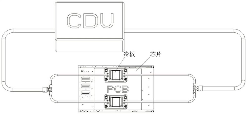
[0028] In order to better understand the implementation of this application, relevant application scenarios of this application will be introduced first. The heat dissipation structure disclosed in the embodiments of the present application can be applied to a two-phase liquid cooling system. An example of the application of two-phase liquid cooling is shown in the figure figure 1 shown. combine figure 1 As shown, the application of two-phase liquid cooling is realized based on t...


PUM


Abstract

The invention discloses a heat dissipation structure. The heat dissipation structure comprises a cold plate used for exchanging heat with a heating device; the fluid pipelines are connected to the two ends of the cold plate and used for conveying heat conduction fluid; the deformation structure is arranged in the fluid pipeline and located at the upstream position of the cold plate, and the deformation structure deforms along with temperature changes. The deformation structure is arranged in fluid management of the heat dissipation structure, so that the shape of the deformation structure can be changed in different temperature environments, the amount of fluid flowing through the fluid pipeline at different temperatures can be controlled based on the relationship between the temperature and the deformation parameter, reasonable heat dissipation capacity is provided for a heating device, and the use requirement of a user is met.

Description

technical field [0001] The present application relates to the technical field of heat dissipation, and more specifically, relates to a heat dissipation structure. Background technique [0002] As the power of today's chips continues to increase, for heat-generating devices with high functional density, ordinary cold plates are no longer sufficient to meet the heat dissipation needs of chips, and two-phase liquid cooling has emerged as the times require. [0003] When two-phase liquid cooling is used to cool multiple heat-generating devices, since the heat generation of multiple heat-generating devices may be inconsistent, when the heat generation of one of the roads far exceeds that of other roads, the evaporation speed of the gas in this road will be particularly fast, resulting in The dryness of the outlet becomes higher and the flow resistance increases, which leads to a decrease in the flow of liquid flowing into this path, which will cause the heat of the chip to not be...

Claims


Application Information

Patent Timeline
Patent Type & Authority Applications(China)
IPC IPC(8): H05K7/20
CPCH05K7/20254H05K7/20281H05K7/20509H05K7/20327G06F1/20G06F2200/201F28D15/0233F28D15/0266F28D15/046H05K7/20336H05K7/20381
Inventor 丁新桐薛欢欢田婷
Owner LENOVO (BEIJING) LTD
Features
  • R&D
  • Intellectual Property
  • Life Sciences
  • Materials
  • Tech Scout
  • Unparalleled Data Quality
  • Higher Quality Content
  • 60% Fewer Hallucinations
Learn More