
Piston assembly equipment for a vacuum bottle

A technology for assembling equipment and vacuum bottles, which is applied in the direction of manufacturing tools, manipulators, hand-held tools, etc., can solve the problems of piston seal failure, lower production efficiency, and pistons are easy to be squeezed and deformed, so as to ensure the sealing effect and small deformation , good practical effect

Active Publication Date: 2022-06-24
ZHEJIANG JINSHENG NEW MATERIALS CO LTD
View PDF10 Cites 0 Cited by
  • Summary
  • Abstract
  • Description
  • Claims
  • Application Information

AI Technical Summary

Problems solved by technology

[0002] The contents of the vacuum bottle can be completely isolated from the air, so as to prevent the product from oxidative deterioration and bacteria breeding due to contact with the air, so it is widely used in the field of cosmetics. When assembling the vacuum bottle, it is necessary to assemble the piston in the vacuum bottle. The manipulator grabs the vacuum bottle and puts it on the outside of the piston, so that the piston is installed inside the vacuum bottle, and then the piston is pushed to the proper position through the mechanism. Since the piston is easy to deform and the piston and the vacuum bottle need interference fit, so in this way Assembling, not only the piston is easily squeezed and deformed, but if the precision of the manipulator is not high, it will easily lead to the failure of the piston seal, and it needs to go through two processes to complete the assembly, which reduces the production efficiency, so it is urgent to improve this

Method used


Image

  • Piston assembly equipment for a vacuum bottle
  • Piston assembly equipment for a vacuum bottle
  • Piston assembly equipment for a vacuum bottle

Examples


Embodiment Construction

[0036]The present invention will be further described below in conjunction with the accompanying drawings and specific embodiments:

[0037] In the description of this specification, the orientation or positional relationship indicated by the terms "upper", "lower", "left", "right", etc. is based on the orientation or positional relationship shown in the accompanying drawings, and is only for the convenience of describing the present invention and The description is simplified rather than indicating or implying that the referred device or unit must have a specific direction, be constructed and operate in a specific orientation, and therefore, should not be construed as limiting the invention.

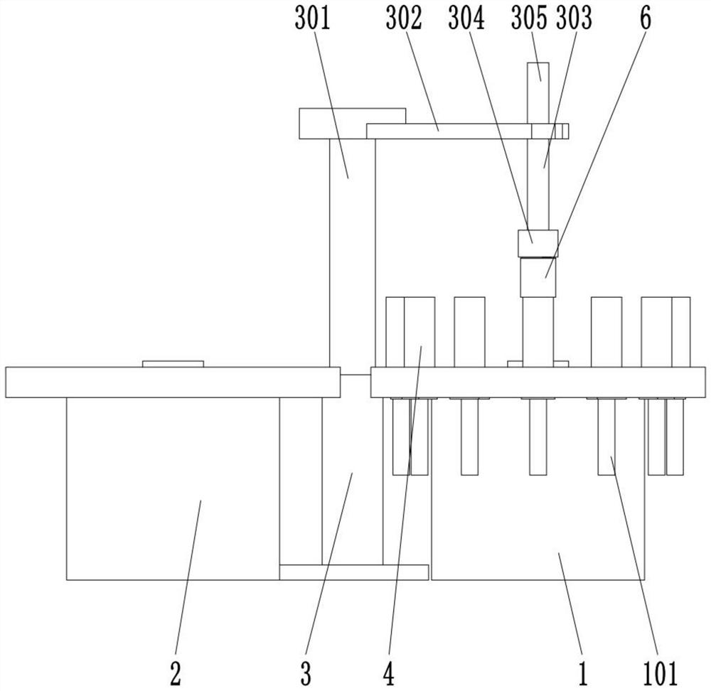
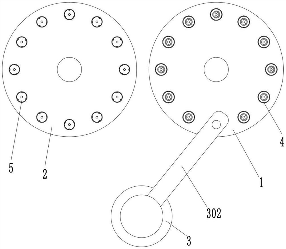
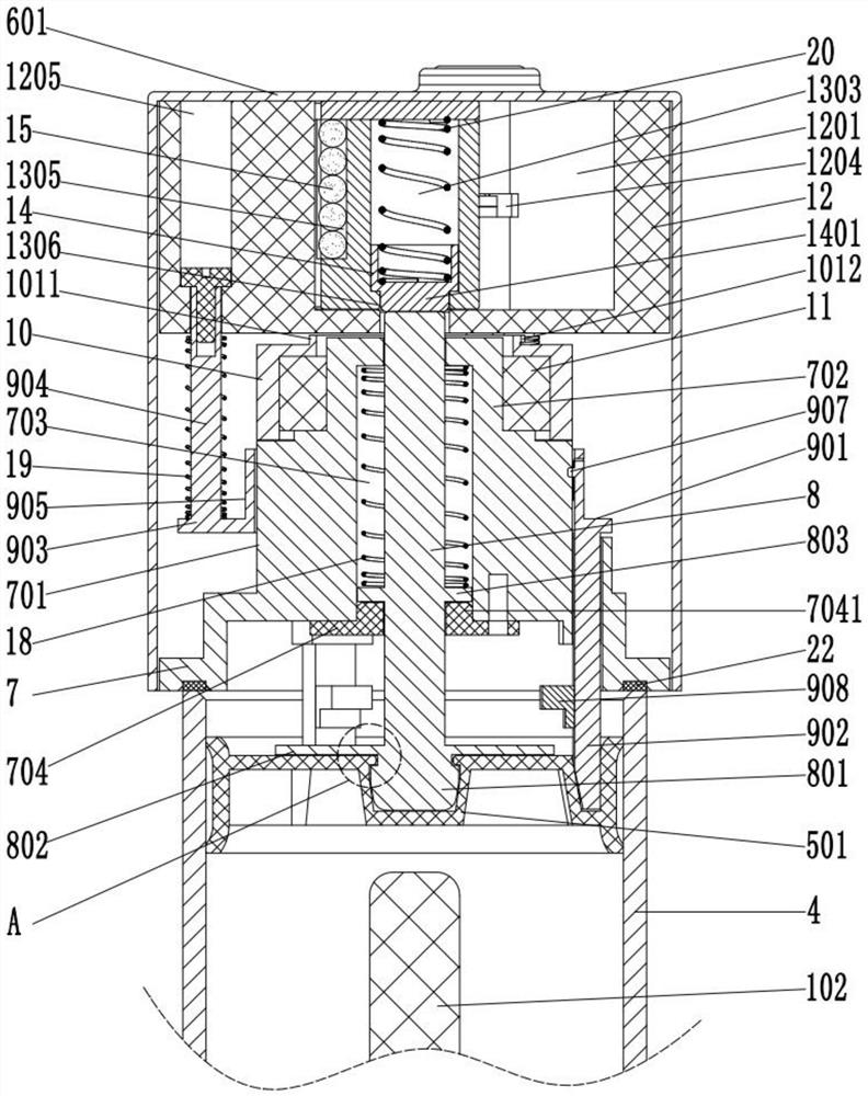
[0038] like Figure 1 to Figure 12 As shown, a piston assembly equipment for a vacuum bottle includes an assembly turntable 1, a piston transfer turntable 2 and a manipulator 3. The upper part of the assembly turntable 1 is provided with a plurality of inverted vacuum bottles 4, and the...


PUM


Abstract

The invention discloses a piston assembly device for a vacuum bottle, which comprises an assembly turntable, a piston transfer turntable and a manipulator. The upper part of the assembly turntable is provided with a plurality of upside-down vacuum bottles, the upper part of the piston transfer turntable is provided with a plurality of pistons, and the manipulator includes a telescopic rod. , the top of the telescopic rod is provided with a rotatable rotating rod, the lower part of the rotating rod is provided with a pressing rod, the upper part of the rotating rod is provided with a second electric push rod, the telescopic rod of the second electric push rod is connected with the pressing rod, and the lower part of the pressing rod is provided with a rotary The connecting sleeve and the lower part of the adapter sleeve are provided with a grabbing device, which can grab the piston so that the manipulator can transfer the piston to the vacuum bottle. The manipulator of the present invention uses the lifting rod to grab the piston while the positioning device limits the position of the piston, and installs the piston into the vacuum bottle, realizing the automatic assembly of the piston, not only reliable clamping, but also greatly improving production efficiency and installation accuracy. Can realize aseptic operation.

Description

technical field [0001] The invention relates to the technical field of vacuum bottle assembly machinery, in particular to a piston assembly device of a vacuum bottle. Background technique [0002] The contents of the vacuum bottle can be completely isolated from the air to prevent the product from oxidizing and deteriorating and breeding bacteria due to contact with air. Therefore, it is widely used in the field of cosmetics. When assembling the vacuum bottle, it is necessary to assemble the piston in the vacuum bottle. The manipulator grabs the vacuum bottle and wraps it on the outside of the piston, so as to install the piston inside the vacuum bottle, and then push the piston to the proper position through the mechanism. Since the piston is easily deformed and the piston and the vacuum bottle need an interference fit, this way Assembly, not only is the piston vulnerable to extrusion deformation, but also easily lead to piston seal failure if the precision of the manipulat...

Claims


Application Information

Patent Timeline
Patent Type & Authority Patents(China)
IPC IPC(8): B25B27/02B25J11/00
CPCB25B27/02B25J11/00
Inventor 阮荣涛
Owner ZHEJIANG JINSHENG NEW MATERIALS CO LTD
Learn More