Adjustable voltage-stabilizing automatic power-off relay

A technology of automatic power-off and relay, applied in relays, emergency protection devices for automatic disconnection, circuits, etc., can solve the problems of reducing the application range of the same type of relays, relay power-off, unfavorable resource saving, etc., to save relay resources, Guarantee the effect of continuous operation

Active Publication Date: 2022-05-06
深圳市恒讯通电子有限公司
View PDF8 Cites 2 Cited by
  • Summary
  • Abstract
  • Description
  • Claims
  • Application Information

AI Technical Summary

Problems solved by technology

[0003] At present, the output voltage of the relay cannot be manually adjusted at will, and the output voltage can only be changed by an external circuit through a series resistor. Different relays are required for electrical appliances corresponding to different voltage requirements, which reduces the number of relays of the same type. The range of application is not conducive to saving resources
[0004] The existing relays will directly cut off the electrical appliances when the input voltage exceeds the tolerance range, and sometimes the input voltage is only temporarily beyond the tolerance range of the relay (instantaneous boost caused by lightning strikes), at this time the relay will The power is still cut off, which will cause trouble when the user uses the electrical appliance, which is not conducive to the user's continuous use of the electrical appliance

Method used


Image

  • Adjustable voltage-stabilizing automatic power-off relay
  • Adjustable voltage-stabilizing automatic power-off relay
  • Adjustable voltage-stabilizing automatic power-off relay

Examples


Embodiment Construction

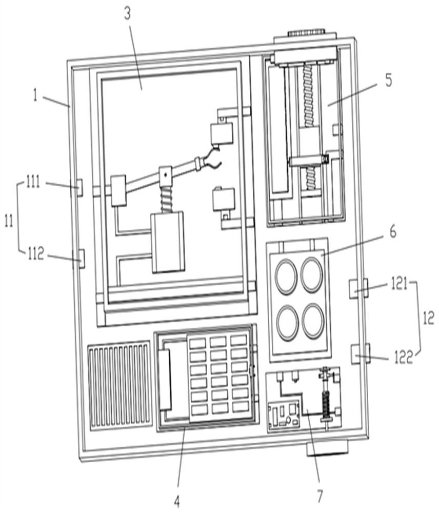
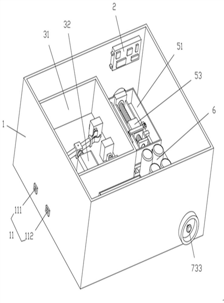
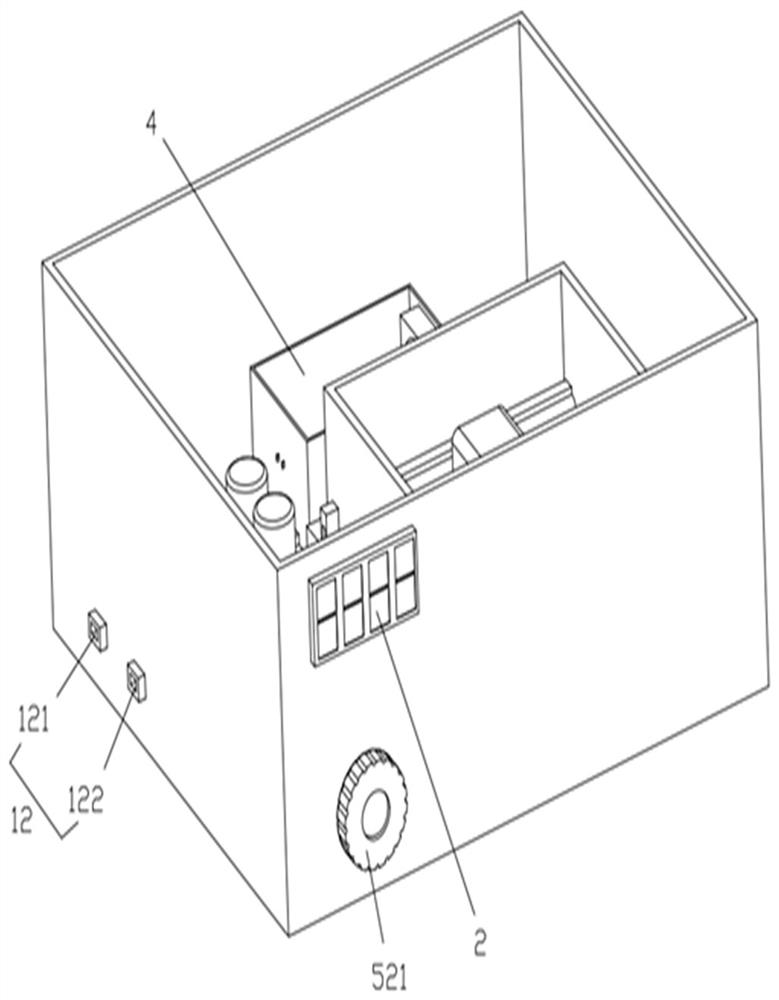
[0042] In order to describe the technical solution of the present invention more clearly and completely, the present invention will be further described below in conjunction with the accompanying drawings.

[0043] Please refer to Figure 1-Figure 12 , the present invention proposes an adjustable voltage-stabilizing automatic power-off relay, comprising a housing 1, a voltmeter 2, a power-on switch 3, a load device 4, a resistance regulator 5, a capacitor 6, and a power-off switch 7, and the housing 1 is provided with The power input part 11, the power output part 12, the power switch 3, the load device 4, the resistance regulator 5, the capacitor 6, and the power cut switch 7 are all fixedly accommodated in the casing 1, and the power cut switch 7 is connected to the power input part 11 and the power switch respectively. One side of the switch 3 is electrically connected to the load device 4, and the other side of the energized switch 3 is electrically connected to the load d...


PUM


Abstract

The invention provides an adjustable voltage-stabilizing automatic power-off relay which comprises a shell, a voltmeter, a power-on switch, a load device, a resistance regulator, a capacitor and a power-off switch, a power input part and a power output part are arranged on the shell, and the power-off switch is electrically connected with the power input part, one side of the power-on switch and the load device. The other side of the power-on switch is electrically connected with the load, the resistance regulator and the capacitor. The voltmeter is fixedly connected to one side of the shell, faces the outside and is connected with the power output part in parallel. According to the invention, the load device is adopted to consume an out-of-range input voltage, and meanwhile, the capacitor is used to carry out follow current on power utilization of an external electric appliance, so that continuous operation of the external electric appliance is guaranteed; and the resistance regulator is adopted to regulate the voltage output by the power supply output part so as to adapt to the requirements of various electric appliances, so that a user can have multiple purposes, and relay resources are saved.

Description

technical field [0001] The invention relates to the technical field of relays, in particular to an adjustable voltage-stabilizing automatic power-off relay. Background technique [0002] The relay is an electrical control device, which is an electrical appliance that causes the controlled quantity to undergo a predetermined step change in the electrical output circuit when the change of the input quantity meets the specified requirements. It has an interactive relationship between the control system and the controlled system. [0003] At present, the output voltage of the relay cannot be manually adjusted at will, and the output voltage can only be changed by means of an external circuit through a series resistor. Different relays are required for electrical appliances corresponding to different voltage requirements, which reduces the number of relays of the same type. The scope of application is not conducive to saving resources. [0004] The existing relays will directly...

Claims


Application Information

Patent Timeline
Patent Type & Authority Applications(China)
IPC IPC(8): H01H47/02H01H47/22H02H3/02H02H3/20
CPCH01H47/02H01H47/22H02H3/02H02H3/20
Inventor 林秀琼
Owner 深圳市恒讯通电子有限公司
Why Eureka
Try Eureka