
Device and method for determining position of intravascular probe

A blood vessel and probe technology, applied in the direction of blood vessel assessment, catheter, application, etc., can solve the problems of injury, damage to blood vessels, and inability to accurately determine

Pending Publication Date: 2022-05-06
安吉科技有限公司
View PDF10 Cites 0 Cited by
  • Summary
  • Abstract
  • Description
  • Claims
  • Application Information

AI Technical Summary

Problems solved by technology

If a clinician cannot determine whether the vessel has been punctured to the desired extent, placing a catheter in an improperly punctured vessel could result in serious injury
This may be related to another problem, where the clinician may not be able to determine exactly when to stop inserting the needle into the vessel, which may also result in damage to the vessel from the inside

Method used


Image

  • Device and method for determining position of intravascular probe
  • Device and method for determining position of intravascular probe
  • Device and method for determining position of intravascular probe

Examples


Embodiment Construction

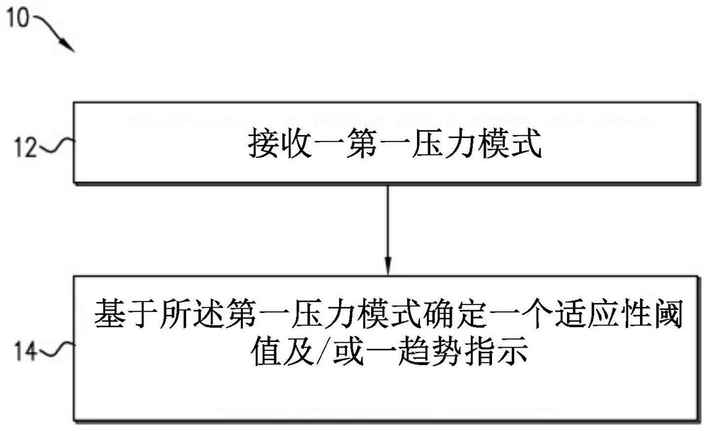
[0112] refer to Figure 1A , schematically illustrates the major steps of a method 10 for determining a position of a distal end of a probe relative to a blood vessel of a patient according to some teachings of the present invention by way of a flowchart. The method 10 includes receiving at 12 a first pressure pattern comprising a plurality of pressure values ​​indicative of a pressure of a fluid while the distal end of the stylet is within the blood vessel, and At 14 said first pressure pattern is processed and at least one adaptive threshold and / or a trend condition indicative of a transition from a first position state to a second position state or vice versa is determined.

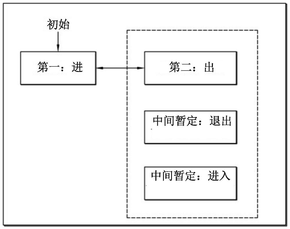
[0113] refer to Figure 1B , schematically illustrates, by means of a block diagram, the principal position states of a distal end of a probe relative to a vessel of a patient, and the possible transitions therebetween. The first position state defines an intravascular condition in which the distal e...


PUM


Abstract

Techniques for determining a position of a distal end of a probe relative to a blood vessel are disclosed. The method includes receiving a first pressure pattern including a plurality of pressure values indicative of a fluid pressure when the distal end of the probe is within the blood vessel, processing the first pressure pattern, and determining at least one adaptive threshold and / or a trend indication. The adaptive threshold represents a transition from a first position state to a second position state, and vice versa. The trend indication represents a specific trend of the pressure mode. The first position state defines an intravascular condition in which the distal end of the probe is located within the blood vessel, and the second position state defines at least one exit condition in which the distal end of the probe is located at least partially outside the blood vessel.

Description

technical field [0001] The present invention generally relates to venipuncture, which is the procedure of gaining access to a blood vessel of a patient. More specifically, the invention relates to determining said position of an intravascular probe. Background technique [0002] References believed to be relevant to the presently disclosed subject matter are listed below: [0003] - U.S. Patent No. 3,785,367 [0004] - U.S. Patent No. 4,215,702 [0005] - U.S. Patent No. 5,314,410 [0006] - U.S. Patent No. 5,520,193 [0007] - U.S. Patent No. 5,954,701 [0008] - U.S. Patent No. 8,574,195 [0009] - US Patent Application No. 2004 / 0243007 [0010] - US Patent Application No. 2011 / 046477 [0011] - US Patent Application No. 2011 / 0060229 [0012] - US Patent Application No. 2011 / 071479 [0013] - US Patent Application No. 2012 / 0172750 [0014] The acknowledgment of the above-mentioned multiple references herein should not be inferred to imply that these references a...

Claims


Application Information

Patent Timeline
Patent Type & Authority Applications(China)
IPC IPC(8): A61M5/00A61B5/00A61B5/0215A61B5/021
CPCA61B5/0215A61B5/065A61B5/6848A61M2205/581A61M2205/583A61M2205/3344A61M5/486A61M5/427A61M2205/18A61M2205/587A61B2562/0247
Inventor 伊斯雷尔·格甚弗拉迪米尔·埃尔曼汉斯·维库伦
Owner 安吉科技有限公司
Learn More