
Devices and methods for determining the position of an intravascular probe

Pending Publication Date: 2022-10-27
ANGIE TECH LTD
View PDF0 Cites 0 Cited by
  • Summary
  • Abstract
  • Description
  • Claims
  • Application Information

AI Technical Summary

Benefits of technology

The device described in this patent helps healthcare professionals know where a probe is located when it is inserted into a patient's skin. This is important because it helps them properly position the probe within a blood vessel in the patient's body. The device uses light to signal its position and can also provide visual information to the practitioner without the need for a screen. The device is designed to prevent accidentally puncturing the opposite wall of the blood vessel and entering the surrounding tissue, which can cause complications during the procedure. The device's housing and probe are both light-permeable, allowing the practitioner to see the surrounding blood vessel during the procedure. The control unit can activate the light and acoustic emitters at the same time to compensate for each other's operation and make the procedure easier to observe.

Problems solved by technology

However, one of the major problems during venipuncture or arterial line placement is difficulty in determination of the exact position of a needle tip inside the skin relative to a blood vessel.
In most conventional systems, venipuncture is performed based on the results of both visual observation and palpation of the skin area to be punctured, and often a blood vessel is not located correctly on a first try.
Another problem is that an observation of blood flow to a flashback chamber is not always a reliable indicator of a blood vessel's wall penetration.
Should a clinician not be able to determine that the blood vessel has been penetrated to the desirable extent catheter placement into an incorrectly punctured blood vessel may cause severe damage.
This may relate to yet another problem, where the clinician may not be able to determine when precisely to stop inserting the needle into the blood vessel, which may also lead to damaging the blood vessel from within.
In fact, correct positioning of a catheter system on any patient with small, deep, faulty or damaged veins, is coupled with the aforesaid problems.

Method used


Image

  • Devices and methods for determining the position of an intravascular probe
  • Devices and methods for determining the position of an intravascular probe
  • Devices and methods for determining the position of an intravascular probe

Examples


Embodiment Construction

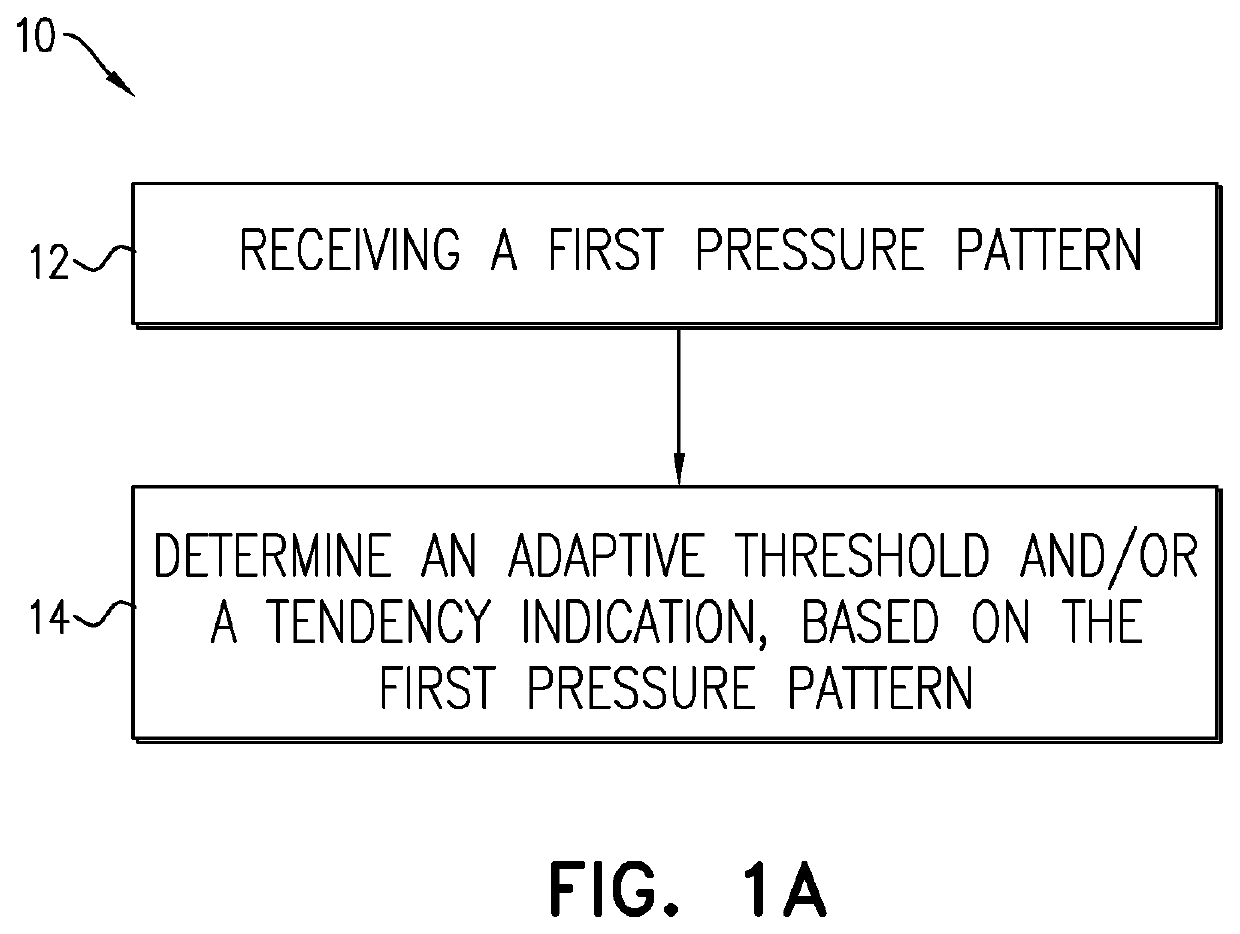
[0111]Reference is made to FIG. 1A schematically illustrating, by way of a flow chart, the main steps of a method 10 for determining a position of a distal end of a probe relative to a blood vessel of a patient according to some teachings of the present invention. The method 10 comprises receiving in 12 a first pressure pattern comprising a plurality of pressure values being indicative of a pressure of a fluid while the distal end of the probe is located inside the blood vessel and in 14 processing the first pressure pattern and determining at least one adaptive threshold and / or a tendency condition being indicative of a transition from a first position state to a second position state, or vice versa.

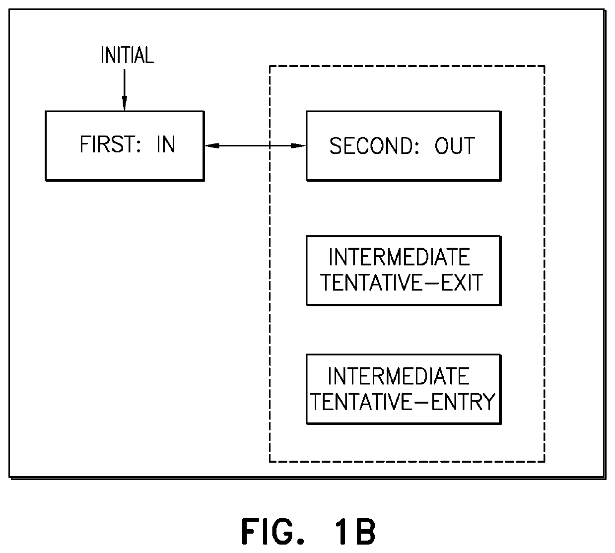
[0112]Reference is made to FIG. 1B schematically illustrating, by way of a block diagram, the main position states of a distal end of a probe relative to a blood vessel of a patient, and the possible transitions between them. The first position state defines an in-blood vessel condition...


PUM


Abstract

The present invention discloses a technique for determining a position of a distal end of a probe relative to a blood vessel. The method comprises receiving a first pressure pattern comprising a plurality of pressure values being indicative of a pressure of a fluid when the distal end of the probe is located inside the blood vessel, processing the first pressure pattern, and determining at least one adaptive threshold and / or a tendency indication. The adaptive threshold is indicative of a transition from a first position state to a second position state, or vice versa. The tendency indication is indicative of a certain trend of the pressure pattern. The first position state defines an in-blood vessel condition in which the distal end of the probe is located inside the blood vessel and the second position state defines at least one exit condition in which the distal end of the probe is located at least partially outside the blood vessel.

Description

TECHNOLOGICAL FIELD[0001]The present invention relates generally to venipuncture, which is the procedure of obtaining access into a blood vessel of a patient. More specifically, the present invention relates to determination of the position of an intravascular probe.BACKGROUND ART[0002]References considered to be relevant as background to the presently disclosed subject matter are listed below:[0003]U.S. Pat. No. 3,785,367[0004]U.S. Pat. No. 4,215,702[0005]U.S. Pat. No. 5,314,410[0006]U.S. Pat. No. 5,520,193[0007]U.S. Pat. No. 5,954,701[0008]U.S. Pat. No. 8,574,195[0009]US patent application No. 2004 / 0243007[0010]US patent application No. 2011 / 046477[0011]US patent application No. 2011 / 0060229[0012]US patent application No. 2011 / 071479[0013]US patent application No. 2012 / 0172750[0014]Acknowledgement of the above references herein is not to be inferred as meaning that these are in any way relevant to the patentability of the presently disclosed subject matter.BACKGROUND[0015]Venipunc...

Claims


Application Information

Patent Timeline
IPC IPC(8): A61B5/06A61B5/0215A61B5/00
CPCA61B5/065A61B5/0215A61B5/6848A61B2562/0247A61M2205/581A61M2205/583A61M2205/3344A61M5/486A61M5/427A61M2205/18A61M2205/587
Inventor GERSHI, ISRAELELMAN, VLADIMIRVERCOULEN, HANS
Owner ANGIE TECH LTD
Learn More